fbpx

EXPRESS SHIPPING WORLDWIDE - DIRECT FROM MANUFACTURER

gca logo new page

2 MOTOR CONTROLS

2.1 Description

The MOTOR CONTROLS are comparable to the typical oscillator controls in other synthesizers. These parameters are typically the foundation for creating a patch.

The eight-motor oscillator block is divided into two groups or voices – MOTOR VOICE 1 and MOTOR VOICE 2. Each MOTOR VOICE consists of 4 motors that can operate in polyphonic, duophonic or monophonic modes. Please refer to the PERFORMANCE INTERFACE / Instructions / POLY SETUP section for polyphonic settings. Each voice’s four motors are controlled with separate controls and parameters.

The first three waveforms, Optical Sine “OPT SINE,” Optical Triangle “OPT SAW,” and Optical Square “OPT SQ,” are generated by an infrared optocoupler (emitter and sensor) that reads three distinct graphical patterns imprinted on reflective optical discs connected to motor shafts. These graphical patterns are located on the discs’ bottom side and represent sine, saw, and square waveforms in graphical form.

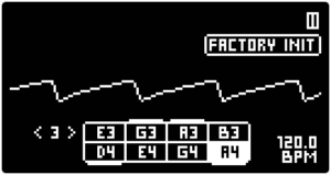
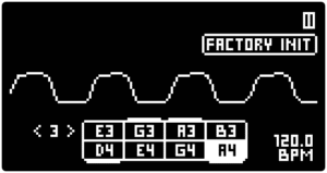
Note: There are inherent imperfections in this system of producing optical waveforms, resulting in a less than precise readout of the graphical sine, saw and square patterns. The audio output produced by the optical discs does not fully match the sound of these waveforms in typical synthesizers. However, we view these imperfections as desirable sound characteristics because they provide a unique source of audio for further synthesis.

The fourth waveshape, labeled “M” for Motor, is an electromagnetic inductive signal collected by eight magnetic pickups. Each pickup is placed next to the electromotor’s rotating coils. This signal generation system is similar to those found in other instruments with inductive pickups, such as the tonewheel organ (which uses electromagnetic induction) and, more distantly, the electric guitar (which uses magnetic induction).

motors uz balta

IN THIS SECTION

2.2 List of parameters

The motors are controlled with one rotary knob VOLUME and two rotary switches WAVE and SCALE for each motor voice.

This list contains an overview of all parameters in this section. For further information refer to the Instructions sub-section.
PARAMETERCONTROLDESCRIPTIONVALUE RANGE
Volume [VOL]VOLUME knobThe volume level of all motors of the given voiceFrom 0 to 100
Waveform [WAVE]WAVE rotary switchWaveshape output selectOptical Sine “OPT SINE”; Optical Saw “OPT SAW”; Optical Square ‘“OPT SQ”; Motor electromagnetic inductive “M”
[SCALE]SCALE rotary switchScale (octave) select32' / 16' / 8' / 4' / 2 '
[TONE MODE]▷ LEFT SCREEN ENCODERAdvanced parameter. Tone tilt mode“SCALE” - the tone tilt follows the SCALE setting; “MANUAL” - manual tone tilt control.
[TONE]◁ RIGHT SCREEN ENCODERAdvanced parameter. Tone tilt manual controlFrom 0 (low boost / high cut) to 100 (low cut / high boost)
VOLUME [VOL]
PARAMETER CONTROL DESCRIPTION VALUE RANGE

Volume [VOL]

VOLUME knob

The volume level of all motors of the given voice.

From 0 to 100

WAVEFORM [WAVE]
PARAMETER CONTROL DESCRIPTION VALUE RANGE

Waveform [WAVE]

WAVE rotary switch

Waveshape output select

Optical Sine “OPT SINE”;
Optical Saw “OPT SAW”;
Optical Square ‘“OPT SQ”;
Motor electromagnetic inductive “M”

[SCALE]
PARAMETER CONTROL DESCRIPTION VALUE RANGE

[SCALE]

SCALE rotary switch

Scale (octave) select

32' / 16' / 8' / 4' / 2 '

[TONE MODE]
PARAMETER CONTROL DESCRIPTION VALUE RANGE

[TONE MODE]

▷ LEFT SCREEN ENCODER

Advanced parameter. Tone tilt mode.

“SCALE” - the tone tilt follows the SCALE setting;
“MANUAL” - manual tone tilt control.

[TONE]
PARAMETER CONTROL DESCRIPTION VALUE RANGE

[TONE]

 RIGHT SCREEN ENCODER

Advanced parameter. Tone tilt manual control.

From 0 (low boost / high cut) to 100 (low cut / high boost)

2.3 Instructions

2.3.1 Setting the VOLUME

Turn the VOLUME knob to adjust the output level of each VOICE, from zero (CCW) to the maximum level (CW).

This is the volume of each motor during the highest point of the AMP ENVELOPE. Unlike the MASTER VOLUME parameter, VOICE VOLUME is saved in PRESETS and is an integral part of the patch. The MASTER VOLUME, on the other hand, is intended to be used as a utility control for setup with other gear

2.3.2 Choosing the waveform – WAVE knob

Turn the WAVE rotary switch to select one of the four Waveforms [WAVE] available for each of the MOTOR Synth’s motor VOICES: Optical Sine “OPT SINE”, Optical Triangle “OPT SAW”, Optical Square “OPT SQ” and Motor electromagnetic inductive “M”.

Tip 1: The main PLAY SCREEN provides an oscilloscope for the final output waveform. To monitor the waveform of a single motor, play one note and turn the MASTER VOLUME to max. Then set the VOLUME of other voices to 0 and set the FILTER TYPE to ALL PASS with the DRIVE and RESONANCE knobs set to minimum.

Tip 2: Since the nature of the instrument does not allow for waveshaping before the FILTER, it may be a good idea to set both MOTOR VOICES to the same SCALE. This will allow for mixing different WAVESHAPES and AMP ENVELOPES to create different waveforms.

2.3.3 Setting the SCALE

The SCALE switch allows you set the octave range in which the motors play all notes. Notes can be entered with the MOTOR Synth’s performance KEYS, ARPEGGIATOR, SEQUENCER, and various MIDI controllers, or triggered via the MOTOR Synth’s assignable CV inputs.

2.3.4 Advanced settings [TONE]

A tilt EQ is applied to the motor output signals before they are mixed and fed into the FILTER. In many patches the EQ tilt settings can be left at their default values. In this case, there is a gradual low boost / high cut in lower SCALE settings, and low cut / high boost in higher SCALE settings. However, some sound design cases can benefit from finer control.

To change the motor output [TONE] turn the VOLUME knob and notice the momentary pop-up [TONE SETT ◁] on the upper-right corner of the screen. While the pop-up is displayed press the ◁ RIGHT SCREEN ENCODER to enter the ANALOG TONE SCREEN.

Use the  LEFT SCREEN ENCODER to toggle the Tone Mode [MODE] from “SCALE” to “MANUAL”.

In the “SCALE” mode, each voice’s EQ tilt [TONE] tracks the respective SCALE switch setting.

In the “MANUAL” mode use the ◁ RIGHT SCREEN ENCODER to adjust the [TONE] for each VOICE individually. Push the ◁ RIGHT SCREEN ENCODER to toggle the cursor between MOTOR VOICES V1 and V2.

Curious?

Leave your email to receive news and subscriber-only deals!