


MENU
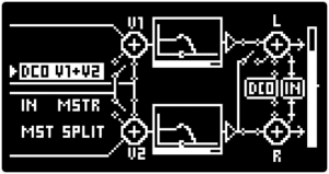
The ROUTING SCREEN provides control over DCO, INPUT and MOTOR VOICE routing.
| PARAMETER | CONTROL | DESCRIPTION | VALUE RANGE |
|---|---|---|---|
| DCO Routing [DCO] | ▷ LEFT SCREEN ENCODER | The DCO output routing setting. The same as [ROUTE TO] parameter in the DCO section | “MSTR” Master output
“V1” Mix with MOTOR VOICE 1 “V2” Mix with MOTOR VOICE 2 “V1+V2” Mix with MOTOR VOICES 1 & 2 |
| INPUT Routing [IN] | ▷ LEFT SCREEN ENCODER | INPUT signal routing. The same as [INPUT ROUTE] parameter in the INPUT SIGNAL PROCESSING section | “MSTR” Master output
“V1” Mix with MOTOR VOICE 1 “V2” Mix with MOTOR VOICE 2 “V1+V2” Mix with MOTOR VOICES 1 & 2 |
| Master Route [MST] | ▷ LEFT SCREEN ENCODER | Master routing. The same as [MASTER ROUTE] parameter in the INPUT SIGNAL PROCESSING section | “MIX L” Both MOTOR VOICES mixed to one channel
“SPLIT” Separate output channel for each MOTOR VOICE (With TRS insert cable) |
| PARAMETER | CONTROL | DESCRIPTION | VALUE RANGE |
|---|---|---|---|
| DCO Routing [DCO] | ▶ LEFT SCREEN ENCODER | The DCO output routing setting. The same as [ROUTE TO] parameter in the DCO section | “MSTR” Master output
“V1” Mix with MOTOR VOICE 1 “V2” Mix with MOTOR VOICE 2 “V1+V2” Mix with MOTOR VOICES 1 & 2 |
| INPUT Routing [IN] | ▶ LEFT SCREEN ENCODER | INPUT signal routing. The same as [INPUT ROUTE] parameter in the INPUT SIGNAL PROCESSING section | “MSTR” Master output
“V1” Mix with MOTOR VOICE 1 “V2” Mix with MOTOR VOICE 2 “V1+V2” Mix with MOTOR VOICES 1 & 2 |
| Master Route [MST] | ▶ LEFT SCREEN ENCODER | Master routing. The same as [MASTER ROUTE] parameter in the INPUT SIGNAL PROCESSING section | “MIX L” Both MOTOR VOICES mixed to one channel
“SPLIT” Separate output channel for each MOTOR VOICE (With TRS insert cable) |
| PARAMETER | CONTROL | DESCRIPTION | VALUE RANGE | ||||
|---|---|---|---|---|---|---|---|
|
DCO Routing [DCO] |
▷ LEFT SCREEN ENCODER |
The DCO output routing setting. The same as [ROUTE TO] parameter in the DCO section |
“MSTR” Master output |
||||
| PARAMETER | CONTROL | DESCRIPTION | VALUE RANGE | ||||
|---|---|---|---|---|---|---|---|
|
INPUT Routing [IN] |
▷ LEFT SCREEN ENCODER |
INPUT signal routing. The same as [INPUT ROUTE] parameter in the INPUT SIGNAL PROCESSING section |
“MSTR” Master output |
||||
| PARAMETER | CONTROL | DESCRIPTION | VALUE RANGE | ||||
|---|---|---|---|---|---|---|---|
|
Master Route [MST] |
▷ LEFT SCREEN ENCODER |
Master routing. The same as [MASTER ROUTE] parameter in the INPUT SIGNAL PROCESSING section |
“MIX L” Both MOTOR VOICES mixed to one channel |
||||
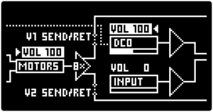
The VOLUME SCREEN provides control over Motor Volume and DCO Volume.
| PARAMETER | CONTROL | DESCRIPTION | VALUE RANGE |
|---|---|---|---|
| Motor Volume [MOTORS VOL] | ▷ LEFT SCREEN ENCODER | Master routing. The same as [MOTOR VOL] parameter in the INPUT SIGNAL PROCESSING section | From 0 to 100 |
| DCO Volume [DCO VOL] | ◁ RIGHT SCREEN ENCODER & DCO VOLUME knob | The volume level of the DCO | From 0 to 100 |
| INPUT Volume [INPUT VOL] | ◁ RIGHT SCREEN ENCODER | The volume level of the INPUT signal | From 0 to 100 |
| PARAMETER | CONTROL | DESCRIPTION | VALUE RANGE |
|---|---|---|---|
| Motor Volume [MOTORS VOL] | ▶ LEFT SCREEN ENCODER | Master routing. The same as [MOTOR VOL] parameter in the INPUT SIGNAL PROCESSING section | From 0 to 100 |
| DCO Volume [DCO VOL] | ◀ RIGHT SCREEN ENCODER & DCO VOLUME knob | The volume level of the DCO | From 0 to 100 |
| INPUT Volume [INPUT VOL] | ◀ RIGHT SCREEN ENCODER | The volume level of the INPUT signal | From 0 to 100 |
| PARAMETER | CONTROL | DESCRIPTION | VALUE RANGE | ||||
|---|---|---|---|---|---|---|---|
|
Motor Volume [MOTORS VOL] |
▷ LEFT SCREEN ENCODER |
Master routing. The same as [MOTOR VOL] parameter in the INPUT SIGNAL PROCESSING section |
From 0 to 100 |
||||
| PARAMETER | CONTROL | DESCRIPTION | VALUE RANGE | ||||
|---|---|---|---|---|---|---|---|
|
DCO Volume [DCO VOL] |
◁ RIGHT SCREEN ENCODER & DCO VOLUME knob |
The volume level of the DCO |
From 0 to 100 |
||||
| PARAMETER | CONTROL | DESCRIPTION | VALUE RANGE | ||||
|---|---|---|---|---|---|---|---|
|
INPUT Volume [INPUT VOL] |
◁ RIGHT SCREEN ENCODER |
The volume level of the INPUT signal |
From 0 to 100 |
||||
| PARAMETER | CONTROL | DESCRIPTION | VALUE RANGE |
|---|---|---|---|
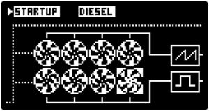
| Startup motor sound [STARTUP] | ▷ LEFT SCREEN ENCODER | The acoustic sound of motors at startup | “ELECTRIC”
“GAS” “DIESEL” |
| PARAMETER | CONTROL | DESCRIPTION | VALUE RANGE |
|---|---|---|---|
| Startup motor sound [STARTUP] | ▶ LEFT SCREEN ENCODER | The acoustic sound of motors at startup | “ELECTRIC”
“GAS” “DIESEL” |
| PARAMETER | CONTROL | DESCRIPTION | VALUE RANGE | ||||
|---|---|---|---|---|---|---|---|
|
Startup motor sound [STARTUP] |
▷ LEFT SCREEN ENCODER |
The acoustic sound of motors at startup |
“ELECTRIC” |
||||
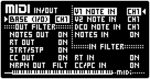
The MIDI SCREEN provides control over MIDI input and output parameters. For extended info on full MIDI implementation refer to MIDI IMPLEMENTATION section.
| PARAMETER | CONTROL | DESCRIPTION | VALUE RANGE |
|---|---|---|---|
| [BASE (I/O)] | ▷ LEFT SCREEN ENCODER | The main MIDI input/output channel | CH1-16
“ALL” “OFF” |
| [NOTES OUT] | ▷ LEFT SCREEN ENCODER | The MIDI note output filter | “ON”
“FILT” |
| [RT OUT] | ▷ LEFT SCREEN ENCODER | MIDI clock output filter | “ON”
“FILT” |
| [STRT/SP] | ▷ LEFT SCREEN ENCODER | Start/Stop message output filter | “ON”
“FILT” |
| [CC OUT] | ▷ LEFT SCREEN ENCODER | Continuous controller output filter | “ON”
“FILT” |
| [NRPN OUT] | ▷ LEFT SCREEN ENCODER | MIDI NRPN output filter | “ON”
“FILT” |
| [V1 NOTE IN] | ◁ RIGHT SCREEN ENCODER | MOTOR VOICE 1 MIDI note inout channel that overrides the [BASE (I/O)]. Also available in the NOTES TO VOICES SCREEN | CH1-16
“ALL” “OFF” |
| [V2 NOTE IN] | ◁ RIGHT SCREEN ENCODER | MOTOR VOICE 2 MIDI note inout channel that overrides the [BASE (I/O)]. Also available in the NOTES TO VOICES SCREEN | CH1-16
“ALL” “OFF” |
| [DCO NOTE IN] | ◁ RIGHT SCREEN ENCODER | DCO MIDI note inout channel that overrides the [BASE (I/O)]. Also available in the NOTES TO VOICES SCREEN | CH1-16
“ALL” “OFF” |
| [NOTES IN] | ◁ RIGHT SCREEN ENCODER | MIDI Note input filter | “ON”
“FILT” |
| [RT IN] | ◁ RIGHT SCREEN ENCODER | MIDI clock input filter | “ON”
“FILT” |
| [CC/PC IN] | ◁ RIGHT SCREEN ENCODER | Continuous controller and program change input filter | “ON”
“FILT” |
| PARAMETER | CONTROL | DESCRIPTION | VALUE RANGE |
|---|---|---|---|
| [BASE (I/O)] | ▶ LEFT SCREEN ENCODER | The main MIDI input/output channel | CH1-16
“ALL” “OFF” |
| [NOTES OUT] | ▶ LEFT SCREEN ENCODER | The MIDI note output filter | “ON”
“FILT” |
| [RT OUT] | ▶ LEFT SCREEN ENCODER | MIDI clock output filter | “ON”
“FILT” |
| [STRT/SP] | ▶ LEFT SCREEN ENCODER | Start/Stop message output filter | “ON”
“FILT” |
| [CC OUT] | ▶ LEFT SCREEN ENCODER | Continuous controller output filter | “ON”
“FILT” |
| [NRPN OUT] | ▶ LEFT SCREEN ENCODER | MIDI NRPN output filter | “ON”
“FILT” |
| [V1 NOTE IN] | ◀ RIGHT SCREEN ENCODERS | MOTOR VOICE 1 MIDI note inout channel that overrides the [BASE (I/O)]. Also available in the NOTES TO VOICES SCREEN | CH1-16
“ALL” “OFF” |
| [V2 NOTE IN] | ◀ RIGHT SCREEN ENCODERS | MOTOR VOICE 2 MIDI note inout channel that overrides the [BASE (I/O)]. Also available in the NOTES TO VOICES SCREEN | CH1-16
“ALL” “OFF” |
| [DCO NOTE IN] | ◀ RIGHT SCREEN ENCODERS | DCO MIDI note inout channel that overrides the [BASE (I/O)]. Also available in the NOTES TO VOICES SCREEN | CH1-16
“ALL” “OFF” |
| [NOTES IN] | ◀ RIGHT SCREEN ENCODERS | MIDI Note input filter | “ON”
“FILT” |
| [RT IN] | ◀ RIGHT SCREEN ENCODERS | MIDI clock input filter | “ON”
“FILT” |
| [CC/PC IN] | ◀ RIGHT SCREEN ENCODERS | Continuous controller and program change input filter | “ON”
“FILT” |
| PARAMETER | CONTROL | DESCRIPTION | VALUE RANGE | ||||
|---|---|---|---|---|---|---|---|
|
[BASE (I/O)] |
▷ LEFT SCREEN ENCODER |
The main MIDI input/output channel |
CH1-16 |
||||
| PARAMETER | CONTROL | DESCRIPTION | VALUE RANGE | ||||
|---|---|---|---|---|---|---|---|
|
[NOTES OUT] |
▷ LEFT SCREEN ENCODER |
MIDI note output filter |
“ON” |
||||
| PARAMETER | CONTROL | DESCRIPTION | VALUE RANGE | ||||
|---|---|---|---|---|---|---|---|
|
[RT OUT] |
▷ LEFT SCREEN ENCODER |
MIDI clock output filter |
“ON” |
||||
| PARAMETER | CONTROL | DESCRIPTION | VALUE RANGE | ||||
|---|---|---|---|---|---|---|---|
|
[STRT/SP] |
▷ LEFT SCREEN ENCODER |
Start/Stop message output filter |
“ON” |
||||
| PARAMETER | CONTROL | DESCRIPTION | VALUE RANGE | ||||
|---|---|---|---|---|---|---|---|
|
[CC OUT] |
▷ LEFT SCREEN ENCODER |
Continuous controller output filter |
“ON” |
||||
| PARAMETER | CONTROL | DESCRIPTION | VALUE RANGE | ||||
|---|---|---|---|---|---|---|---|
|
Hold [H] |
AMP ENV encoder; Push to jump to the parameter; Turn to change the parameter |
The hold stage time in seconds (available only when the ADSHR envelope type is selected) |
From 0.00 to 5.00 |
||||
| PARAMETER | CONTROL | DESCRIPTION | VALUE RANGE | ||||
|---|---|---|---|---|---|---|---|
|
[NRPN OUT] |
▷ LEFT SCREEN ENCODER |
MIDI NRPN output filter |
“ON” |
||||
| PARAMETER | CONTROL | DESCRIPTION | VALUE RANGE | ||||
|---|---|---|---|---|---|---|---|
|
[V1 NOTE IN] |
◁ RIGHT SCREEN ENCODERS |
MOTOR VOICE 1 MIDI note inout channel that overrides the [BASE (I/O)]. Also available in the NOTES TO VOICES SCREEN |
CH1-16 |
||||
| PARAMETER | CONTROL | DESCRIPTION | VALUE RANGE | ||||
|---|---|---|---|---|---|---|---|
|
[V2 NOTE IN] |
◀ RIGHT SCREEN ENCODERS |
MOTOR VOICE 2 MIDI note inout channel that overrides the [BASE (I/O)]. Also available in the NOTES TO VOICES SCREEN |
CH1-16 |
||||
| PARAMETER | CONTROL | DESCRIPTION | VALUE RANGE | ||||
|---|---|---|---|---|---|---|---|
|
[DCO NOTE IN] |
◁ RIGHT SCREEN ENCODERS |
DCO MIDI note inout channel that overrides the [BASE (I/O)]. Also available in the NOTES TO VOICES SCREEN |
CH1-16 |
||||
| PARAMETER | CONTROL | DESCRIPTION | VALUE RANGE | ||||
|---|---|---|---|---|---|---|---|
|
[NOTES IN] |
◀ RIGHT SCREEN ENCODERS |
MIDI Note input filter |
“ON” |
||||
| PARAMETER | CONTROL | DESCRIPTION | VALUE RANGE | ||||
|---|---|---|---|---|---|---|---|
|
[RT IN] |
◁ RIGHT SCREEN ENCODERS |
MIDI clock input filter |
“ON” |
||||
| PARAMETER | CONTROL | DESCRIPTION | VALUE RANGE | ||||
|---|---|---|---|---|---|---|---|
|
[CC/PC IN] |
◁ RIGHT SCREEN ENCODERS |
Continuous controller and program change input filter |
“ON” |
||||
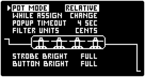
The PARAMETER SETTINGS AND BRIGHTNESS SCREEN provides control over potentiometer and encoder settings, as well as strobe and KEYPAD and button brightness.
| PARAMETER | CONTROL | DESCRIPTION | VALUE RANGE |
|---|---|---|---|
| [POT MODE] | ▷ LEFT SCREEN ENCODER | Determines how potentiometers function when the physical position does not match with the value loaded with a PRESET | “RELATIVE” - remaining value range of a given parameter is spread across the available physical range of the potentiometer - thus ensuring smooth knob behaviour at all times.
“JUMP” - a change of the physical position of a potentiometer immediately affects the parameter. “CATCH” - the parameter is affected only after the potentiometer crosses the parameter value |
| [WHILE ASSIGN] | ▷ LEFT SCREEN ENCODER | Determines if physical potentiometer and encoder adjustments affect parameters during the MOD ASSIGN process | “CHANGE” - parameters are affected normally
“FREEZE” - parameters are not affected |
| [POPUP TIMEOUT] | ▷ LEFT SCREEN ENCODER | Determines the time duration of pop-up messages | From 1 to 10 seconds |
| [FILTER UNITS] | ▷ LEFT SCREEN ENCODER | Determines the FILTER [CUTOFF] measurement units | “CENTS”
“Hz” |
| [STROBE BRIGHT] | ▷ LEFT SCREEN ENCODER | The brightness of the motor bay strobe | “FULL”
“HALF” “DIM” |
| [BUTTON BRIGHT] | ▷ LEFT SCREEN ENCODER | The brightness of keys and buttons | “FULL”
“HALF” “DIM” |
| PARAMETER | CONTROL | DESCRIPTION | VALUE RANGE |
|---|---|---|---|
| [POT MODE] | ▶ LEFT SCREEN ENCODER | Determines how potentiometers function when the physical position does not match with the value loaded with a PRESET | “RELATIVE” - remaining value range of a given parameter is spread across the available physical range of the potentiometer - thus ensuring smooth knob behaviour at all times.
“JUMP” - a change of the physical position of a potentiometer immediately affects the parameter. “CATCH” - the parameter is affected only after the potentiometer crosses the parameter value |
| [WHILE ASSIGN] | ▶ LEFT SCREEN ENCODER | Determines if physical potentiometer and encoder adjustments affect parameters during the MOD ASSIGN process | “CHANGE” - parameters are affected normally
“FREEZE” - parameters are not affected |
| [POPUP TIMEOUT] | ▶ LEFT SCREEN ENCODER | Determines the time duration of pop-up messages | From 1 to 10 seconds |
| [FILTER UNITS] | ▶ LEFT SCREEN ENCODER | Determines the FILTER [CUTOFF] measurement units | “CENTS”
“Hz” |
| [STROBE BRIGHT] | ▶ LEFT SCREEN ENCODER | The brightness of the motor bay strobe | “FULL”
“HALF” “DIM” |
| [BUTTON BRIGHT] | ▶ LEFT SCREEN ENCODER | The brightness of keys and buttons | “FULL”
“HALF” “DIM” |
| PARAMETER | CONTROL | DESCRIPTION | VALUE RANGE | |||
|---|---|---|---|---|---|---|
|
[POT MODE] |
▷ LEFT SCREEN ENCODER |
Determines how potentiometers function when the physical position does not match with the value loaded with a PRESET |
“RELATIVE” – remaining value range of a given parameter is spread across the available physical range of the potentiometer – thus ensuring smooth knob behaviour at all times. |
|||
| PARAMETER | CONTROL | DESCRIPTION | VALUE RANGE | |||
|---|---|---|---|---|---|---|
|
[WHILE ASSIGN] |
▷ LEFT SCREEN ENCODER |
Determines if physical potentiometer and encoder adjustments affect parameters during the MOD ASSIGN process |
“CHANGE” – parameters are affected normally. |
|||
| PARAMETER | CONTROL | DESCRIPTION | VALUE RANGE | |||
|---|---|---|---|---|---|---|
|
[POPUP TIMEOUT] |
▷ LEFT SCREEN ENCODER |
Determines the time duration of pop-up messages |
From 1 to 10 seconds |
|||
| PARAMETER | CONTROL | DESCRIPTION | VALUE RANGE | |||
|---|---|---|---|---|---|---|
|
[FILTER UNITS] |
▷ LEFT SCREEN ENCODER |
Determines the FILTER [CUTOFF] measurement units |
“CENTS” |
|||
| PARAMETER | CONTROL | DESCRIPTION | VALUE RANGE | |||
|---|---|---|---|---|---|---|
|
[STROBE BRIGHT] |
▷ LEFT SCREEN ENCODER |
The brightness of the motor bay strobe |
“FULL” |
|||
| PARAMETER | CONTROL | DESCRIPTION | VALUE RANGE | |||
|---|---|---|---|---|---|---|
|
[BUTTON BRIGHT] |
▷ LEFT SCREEN ENCODER |
The brightness of keys and buttons |
“FULL” |
|||
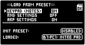
The PRESETS SETTINGS SCREEN provides control over PRESET loading settings as well as information about the selected INIT PRESET and currently loaded PRESET.
| PARAMETER | CONTROL | DESCRIPTION | VALUE RANGE |
|---|---|---|---|
| [KEYPAD (NOTES)] | ▷ LEFT SCREEN ENCODER | Determines if the KEYPAD SETUP parameters of each PRESET are loaded | “ON”
“OFF” |
| [RND SETTINGS] | ▷ LEFT SCREEN ENCODER | Determines if the RANDOM GENERATOR parameters of each PRESET are loaded | “ON”
“OFF” |
| [ARP SETTINGS] | ▷ LEFT SCREEN ENCODER | Determines if the ARPEGGIATOR parameters of each PRESET are loaded | “ON”
“OFF” |
| PARAMETER | CONTROL | DESCRIPTION | VALUE RANGE |
|---|---|---|---|
| [KEYPAD (NOTES)] | ▶ LEFT SCREEN ENCODER | Determines if the KEYPAD SETUP parameters of each PRESET are loaded | “ON”
“OFF” |
| [RND SETTINGS] | ▶ LEFT SCREEN ENCODER | Determines if the RANDOM GENERATOR parameters of each PRESET are loaded | “ON”
“OFF” |
| [ARP SETTINGS] | ▶ LEFT SCREEN ENCODER | Determines if the ARPEGGIATOR parameters of each PRESET are loaded | “ON”
“OFF” |
| PARAMETER | CONTROL | DESCRIPTION | VALUE RANGE | ||||
|---|---|---|---|---|---|---|---|
|
[KEYPAD (NOTES)] |
▷ LEFT SCREEN ENCODER |
Determines if the KEYPAD SETUP parameters of each PRESET are loaded |
“ON” |
||||
| PARAMETER | CONTROL | DESCRIPTION | VALUE RANGE | ||||
|---|---|---|---|---|---|---|---|
|
[RND SETTINGS] |
▷ LEFT SCREEN ENCODER |
Determines if the RANDOM GENERATOR parameters of each PRESET are loaded |
“ON” |
||||
| PARAMETER | CONTROL | DESCRIPTION | VALUE RANGE | ||||
|---|---|---|---|---|---|---|---|
|
[ARP SETTINGS] |
▷ LEFT SCREEN ENCODER |
Determines if the ARPEGGIATOR parameters of each PRESET are loaded |
“ON” |
||||
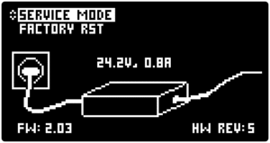
The SERVICE SCREEN provides information about the FIRMWARE version, power supply status as well as access to the SERVICE MODE and option to reset the MOTOR Synth to the factory settings.
| PARAMETER | CONTROL | DESCRIPTION | VALUE RANGE |
|---|---|---|---|
| [SERVICE MODE] | ▷ LEFT SCREEN ENCODER | Puts the MOTOR Synth in the SERVICE MODE | NA |
| [FACTORY RESET] | ▷ LEFT SCREEN ENCODER | Resets the MOTOR Synth to factory settings. This does not affect PRESETS and PROJECTS | NA |
| PARAMETER | CONTROL | DESCRIPTION | VALUE RANGE |
|---|---|---|---|
| [SERVICE MODE] | ▶ LEFT SCREEN ENCODER | Puts the MOTOR Synth in the SERVICE MODE | NA |
| [FACTORY RESET] | ▶ LEFT SCREEN ENCODER | Resets the MOTOR Synth to factory settings. This does not affect PRESETS and PROJECTS | NA |
| PARAMETER | CONTROL | DESCRIPTION | VALUE RANGE | ||||
|---|---|---|---|---|---|---|---|
|
[SERVICE MODE] |
▷ LEFT SCREEN ENCODER |
Puts the MOTOR Synth in the SERVICE MODE |
NA |
||||
| PARAMETER | CONTROL | DESCRIPTION | VALUE RANGE | ||||
|---|---|---|---|---|---|---|---|
|
[FACTORY RESET] |
▷ LEFT SCREEN ENCODER |
Resets the MOTOR Synth to factory settings. This does not affect PRESETS and PROJECTS |
NA |
||||
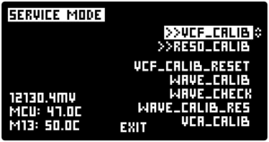
The MOTOR Synth detects any need for calibration upon startup and offers to perform calibration if needed. Additionally, the calibration can be manually started in the SERVICE MODE.
The SERVICE MODE offers the FILTER calibration [VCF_CALIB] and [RESO CALIB], Optical Waveform calibration [WAVE_CALIB] and amplifier calibration [VCA_CALIB].
Note: Disconnect the MOTOR Synth from speakers and headphones when performing calibration, as it may produce loud output.

Nobody knows why that padlock is there.