
MENU
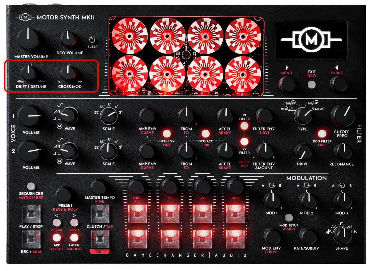
Even though the MODULATION section of the MOTOR Synth is assignable to almost any parameter, these two modulation effects are featured in the MASTER section of the instrument for their character and utility.
DRIFT is an irregular vibrato effect applied to each individual motor and digital oscillator. Designed to emulate the warble and unstable behavior of vintage analog oscillators the effect is not limited to only mimicking instability. Chorusing and aggressive vibrato effects are equally possible. The MOTOR Synth achieves this effect in an analog way by modulating the speed of individual motors and digital oscillators so that they drift around their target frequency.
DETUNE is also an analog effect achieved by introducing errors / offsets in the target frequencies of all notes. The random offsets are retriggered, so each new note is slightly sharp or flat. This results in a slightly more static effect with frequency beating and dissonances in higher settings. In lower settings the DETUNE can provide the subtle and musically pleasing instability not typically associated with perfectly tuned electronic instruments.
CROSS MOD is an amplitude cross-modulation between both MOTOR VOICES and DCO. The effect produces aggressive and raspy sounds which provide rich harmonic content for further filtering. As the effect is based on VOICE cross-modulation, it is fully dependent on the pitch performance of each VOICE. The CROSS MOD effect does not use the actual VOICE output as the modulator signal, but rather a signal created based on the current [WAVE] settings and pitch of the most recently played note. This can be used to alter the CROSS MOD modulator without changing the VOICE settings.
All three of these effects are controlled by simple front panel controls. However, all three have several advanced parameters in the dedicated screens that can greatly change the outcoming effect.
DRIFT and DETUNE effects are controlled with the DRIFT | DETUNE knob in counterclockwise and clockwise directions respectively. CROSS MOD is controlled with the CROSS MOD knob. Each effect has a dedicated screen with additional parameters adjusted with the ▷ LEFT & ◁ RIGHT SCREEN ENCODERS.
The lists below contain an overview of all parameters in this section. For further information refer to the Instructions sub-section.
| PARAMETER | CONTROL | DESCRIPTION | VALUE RANGE |
|---|---|---|---|
| [DRIFT] | DRIFT | DETUNE knob counterclockwise | The depth of DRIFT effect | From 0 to 50 |
| [DETUNE] | DRIFT | DETUNE knob clockwise | The depth of DETUNE effect | From 0 to 50 |
| [RATE X] | ▷ LEFT SCREEN ENCODER | The DRIFT frequency multiplier | From 0.06 to 16 |
| V1 Status [V1 DET] | ▷ LEFT SCREEN ENCODER | MOTOR VOICE 1 effect status | “ON”; “OFF” |
| V2 Status [V2 DET] | ▷ LEFT SCREEN ENCODER | MOTOR VOICE 2 effect status | “ON”; “OFF” |
| DCO Status [DCO DET] | ▷ LEFT SCREEN ENCODER | DCO effect status | “ON”; “OFF” |
| PARAMETER | CONTROL | DESCRIPTION | VALUE RANGE | ||||
|---|---|---|---|---|---|---|---|
|
[DRIFT] |
DRIFT | DETUNE knob counterclockwise |
The depth of DRIFT effect |
From 0 to 50 |
||||
| PARAMETER | CONTROL | DESCRIPTION | VALUE RANGE | ||||
|---|---|---|---|---|---|---|---|
|
[DETUNE] |
DRIFT | DETUNE knob clockwise |
The depth of DETUNE effect |
From 0 to 50 |
||||
| PARAMETER | CONTROL | DESCRIPTION | VALUE RANGE | ||||
|---|---|---|---|---|---|---|---|
|
[RATE X] |
▷ LEFT SCREEN ENCODER |
The DRIFT frequency multiplier |
From 0.06 to 16 |
||||
| PARAMETER | CONTROL | DESCRIPTION | VALUE RANGE | ||||
|---|---|---|---|---|---|---|---|
|
V1 Status [V1 DET] |
▷ LEFT SCREEN ENCODER |
MOTOR VOICE 1 effect status |
“ON”; “OFF” |
||||
| PARAMETER | CONTROL | DESCRIPTION | VALUE RANGE | ||||
|---|---|---|---|---|---|---|---|
|
V2 Status [V2 DET] |
▷ LEFT SCREEN ENCODER |
MOTOR VOICE 2 effect status |
“ON”; “OFF” |
||||
| PARAMETER | CONTROL | DESCRIPTION | VALUE RANGE | ||||
|---|---|---|---|---|---|---|---|
|
DCO Status [DCO DET] |
▷ LEFT SCREEN ENCODER |
DCO effect status |
“ON”; “OFF” |
||||
| PARAMETER | CONTROL | DESCRIPTION | VALUE RANGE |
|---|---|---|---|
| [DEPTH] | CROSS MOD knob | The depth of CROSS MOD. When turned counterclockwise V1 is the modulator. When turned clockwise V2 is the modulator. | From -100 (V1 is modulator) through 0 (no CROSS MOD) to 100 (V2 is modulator) |
| Pulse Width [PW] | ◁ RIGHT SCREEN ENCODER | The Pulse Width control of the modulator signal | From 0 to 1 |
| [SCALE] | ◁ RIGHT SCREEN ENCODER | Octave offset of the modulator signal | From -2 to +5 |
| V1 Status [V1] | ▷ LEFT SCREEN ENCODER | MOTOR VOICE 1 effect status | “ON”; “OFF” |
| V2 Status [V2] | ▷ LEFT SCREEN ENCODER | MOTOR VOICE 2 effect status | “ON”; “OFF” |
| DCO Status [DCO] | ▷ LEFT SCREEN ENCODER | DCO effect status | “ON”; “OFF” |
| PARAMETER | CONTROL | DESCRIPTION | VALUE RANGE | ||||
|---|---|---|---|---|---|---|---|
|
[DEPTH] |
CROSS MOD knob |
The depth of CROSS MOD. When turned counterclockwise V1 is the modulator. When turned clockwise V2 is the modulator. |
From -100 (V1 is modulator) through 0 (no CROSS MOD) to 100 (V2 is modulator) |
||||
| PARAMETER | CONTROL | DESCRIPTION | VALUE RANGE | ||||
|---|---|---|---|---|---|---|---|
|
Pulse Width [PW] |
◁ RIGHT SCREEN ENCODER |
The Pulse Width control of the modulator signal |
From 0 to 1 |
||||
| PARAMETER | CONTROL | DESCRIPTION | VALUE RANGE | ||||
|---|---|---|---|---|---|---|---|
|
[SCALE] |
◁ RIGHT SCREEN ENCODER |
Octave offset of the modulator signal |
From -2 to +5 |
||||
| PARAMETER | CONTROL | DESCRIPTION | VALUE RANGE | ||||
|---|---|---|---|---|---|---|---|
|
V1 Status [V1] |
▷ LEFT SCREEN ENCODER |
MOTOR VOICE 1 effect status |
“ON”; “OFF” |
||||
| PARAMETER | CONTROL | DESCRIPTION | VALUE RANGE | ||||
|---|---|---|---|---|---|---|---|
|
V2 Status [V2] |
▷ LEFT SCREEN ENCODER |
MOTOR VOICE 2 effect status |
“ON”; “OFF” |
||||
| PARAMETER | CONTROL | DESCRIPTION | VALUE RANGE | ||||
|---|---|---|---|---|---|---|---|
|
DCO Status [DCO] |
▷ LEFT SCREEN ENCODER |
DCO effect status |
“ON”; “OFF” |
||||
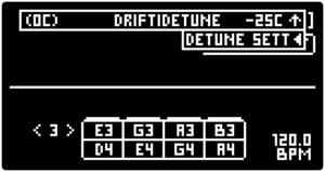
Turn the DRIFT | DETUNE knob counterclockwise to set the depth of DRIFT effect and turn the knob clockwise to set the depth of DETUNE effect.
To set the additional parameters of both effects enter the DETUNE SCREEN by turning the DRIFT | DETUNE knob and notice the momentary pop-up “DETUNE SETT” on the upper-right corner of the screen. While the pop-up is displayed press the ◁ RIGHT SCREEN ENCODER to enter the DETUNE SCREEN.
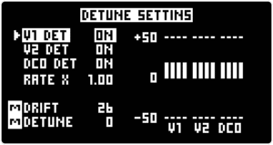
The graph on the right side displays a graphical representation of each motor’s and digital oscillator’s offset from target pitch.
Push the ▷ LEFT SCREEN ENCODER to highlight the [V1], [V2] and [DCO] DRIFT and DETUNE effect statuses and turn the encoder to switch the effect “ON” or “OFF” for each VOICE individually.
Push the ▷ LEFT SCREEN ENCODER to highlight the [RATE X] and turn the encoder to set the value. This parameter is a multiplier for the predefined DRIFT frequency. With setting below 1, the frequency is divided producing slow motor and digital oscillator pitch movement. Settings above 1 multiply the frequency producing more pronounced effects and can be utilized for chorusing effect.
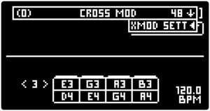
Turn the CROSS MOD knob counterclockwise to set the CROSS MOD [DEPTH] with the MOTOR VOICE 1 as the modulator. The frequency and waveform of V1 will be used to modulate the amplitude of all VOICES. Turn the knob clockwise to set the CROSS MOD [DEPTH] with the MOTOR VOICE 2 as the modulator.
To set the additional parameters enter the CROSS MOD SCREEN by turning the CROSS MOD knob and notice the momentary pop-up “XMOD SETT” on the upper-right corner of the screen. While the pop-up is displayed press the ◁ RIGHT SCREEN ENCODER to enter the CROSS MOD SCREEN.
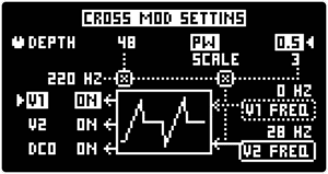
The screen provides modulator frequency and waveform readout.
Use the ◁ RIGHT SCREEN ENCODER to set the Pulse Width [PW] and [SCALE] of the modulator signal. These parameters modify the waveform which is otherwise determined by the MOTOR VOICE’S [WAVE] and [SCALE] parameters.
The Pulse Width [PW] determines the pulse width of the waveform. This parameter is also available for non-square wave waveforms.]
The [SCALE] parameter introduces octave offset for the modulator signal. Higher settings will introduce high-frequency harmonics, but lower settings can introduce sub-audio rate cross-modulation which will result in a note dependent tremolo effect.
Push the ▷ LEFT SCREEN ENCODER to highlight the [V1], [V2] and [DCO] CROSS MOD effect statuses and turn the encoder to switch the effect “ON” or “OFF” for each VOICE individually.
Note: By default the modulator voice modulates all VOICES including itself. It is possible to override this using the VOICE effect status toggles.