
MENU
The MOTOR Synth features a 1 / 4 ‘ audio input jack on the back panel and the incoming audio signal can be used and routed in several ways:
The input signal can be mixed with the MOTOR Synth voices before (pre) and after (post) the FILTER.
Note: The variable INPUT gain allows the use of audio signals of various amplitudes, including microphone level without requiring a separate preamp. This is useful for using the microphone INPUT for gating, ducking and triggering sounds. However, for use with the VOCODER and for mixing the INPUT with the MOTOR Synth’s VOICES it is advised to use a separate microphone preamp to achieve better signal to noise ratio.
INPUT signal routing is managed in the INPUT MENU SCREEN. Push ALT + ◁ RIGHT SCREEN ENCODER / IN to access the screen.
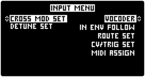
Turn the ◁ RIGHT SCREEN ENCODER to highlight one of the INPUT routing options and push the encoder to select: VOCODER, IN ENV FOLLOW (envelope follower) or ROUTE SET (INPUT routing). Each has a separate set of parameters and this section is organized accordingly.
The lists below contain an overview of all parameters in this section. For further information refer to the Instructions sub-section.
| PARAMETER | CONTROL | DESCRIPTION | VALUE RANGE |
|---|---|---|---|
| VOCODER Status [VOC] | ▷ LEFT SCREEN ENCODER | VOCODER Status | “ON”
“OFF” |
| Carrier Clean Blend [BLEND] | ▷ LEFT SCREEN ENCODER | The volume of the carrier signal (MOTOR Synth VOICES) blend | From 0.0 to 1.0 |
| INPUT Gain [IN DB] | ▷ LEFT SCREEN ENCODER | INPUT gain boost or cut i dB | From -20 dB to +40 dB |
| Number of Bands [BANDS] | ◁ RIGHT SCREEN ENCODER | The number of VOCODER bands | 4, 8, 12, 16* |
| Gain of the Center Frequency [Q] | ◁ RIGHT SCREEN ENCODER | The center (peak) frequency of the carrier’s (MOTOR Synth’s) graphic EQ | From 0.0 to 2.0 |
| Carrier Graphic EQ Center Frequency [FC] | ◁ RIGHT SCREEN ENCODER | The gain of the graphic EQ center frequency | From 0.0 to 2.0 |
| Band Width [BW] | ◁ RIGHT SCREEN ENCODER | Band width of each VOCODER band | From -0.5 to 0.5 |
| Left Side Band Frequency [LSB] | ◁ RIGHT SCREEN ENCODER | The frequency of the left side band | From 0.0 kHz to 10.0 kHz |
| Right Side Band Frequency [RSB] | ◁ RIGHT SCREEN ENCODER | The frequency of the right side band | From 0.5 kHz to 15.0 kHz |
| PARAMETER | CONTROL | DESCRIPTION | VALUE RANGE | ||
|---|---|---|---|---|---|
|
VOCODER Status [VOC] |
▷ LEFT SCREEN ENCODER |
VOCODER Status |
“ON” |
||
| PARAMETER | CONTROL | DESCRIPTION | VALUE RANGE | ||
|---|---|---|---|---|---|
|
Carrier Clean Blend [BLEND] |
▷ LEFT SCREEN ENCODER |
The volume of the carrier signal (MOTOR Synth VOICES) blend |
From 0.0 to 1.0 |
||
| PARAMETER | CONTROL | DESCRIPTION | VALUE RANGE | ||
|---|---|---|---|---|---|
|
INPUT Gain [IN DB] |
▷ LEFT SCREEN ENCODER |
INPUT gain boost or cut i dB |
From -20 dB to +40 dB |
||
| PARAMETER | CONTROL | DESCRIPTION | VALUE RANGE | ||
|---|---|---|---|---|---|
|
Number of Bands [BANDS] |
◁ RIGHT SCREEN ENCODER |
The number of VOCODER bands |
4, 8, 12, 16* |
||
| PARAMETER | CONTROL | DESCRIPTION | VALUE RANGE | ||
|---|---|---|---|---|---|
|
Gain of the Center Frequency [Q] |
◁ RIGHT SCREEN ENCODER |
The gain of the graphic EQ center frequency |
From 0.0 to 2.0 |
||
| PARAMETER | CONTROL | DESCRIPTION | VALUE RANGE | ||
|---|---|---|---|---|---|
|
Carrier Graphic EQ Center Frequency [FC] |
◁ RIGHT SCREEN ENCODER |
The center (peak) frequency of the carrier’s (MOTOR Synth’s) graphic EQ |
From 0.0 to 2.0 |
||
| PARAMETER | CONTROL | DESCRIPTION | VALUE RANGE | ||
|---|---|---|---|---|---|
|
Band Width [BW] |
◁ RIGHT SCREEN ENCODER |
Band width of each VOCODER band |
From -0.5 to 0.5 |
||
| PARAMETER | CONTROL | DESCRIPTION | VALUE RANGE | ||
|---|---|---|---|---|---|
|
Left Side Band Frequency [LSB] |
◁ RIGHT SCREEN ENCODER |
The frequency of the left side band |
From 0.0 kHz to 10.0 kHz |
||
| PARAMETER | CONTROL | DESCRIPTION | VALUE RANGE | ||
|---|---|---|---|---|---|
|
Right Side Band Frequency [RSB] |
◁ RIGHT SCREEN ENCODER |
The frequency of the right side band |
From 0.5 kHz to 15.0 kHz |
||
* The maximum number of bands can be limited to 12 or 8 bands due to processing limitations. See the Instructions section for more information.
| PARAMETER | CONTROL | DESCRIPTION | VALUE RANGE |
|---|---|---|---|
| VOICE 1 Status [V1] | ▷ LEFT SCREEN ENCODER | INPUT envelope follower status for MOTOR VOICE 1 | “ON”
“OFF” |
| VOICE 2 Status [V2] | ▷ LEFT SCREEN ENCODER | INPUT envelope follower status for MOTOR VOICE 2 | “ON”
“OFF” |
| DCO Status [DCO] | ▷ LEFT SCREEN ENCODER | INPUT envelope follower status for DCO | “ON”
“OFF” |
| ARPEGGIATOR Trigger Status [ARP] | ▷ LEFT SCREEN ENCODER | INPUT trigger assignment to ARPEGGIATOR | “ON”
“OFF” |
| SEQUENCER Trigger Status [SEQ] | ◁ RIGHT SCREEN ENCODER | INPUT trigger assignment to SEQUENCER | “ON”
“OFF” |
| [MODE] | ◁ RIGHT SCREEN ENCODER | INPUT toggle between GATE and DUCKING | ‘’OFF”
"DUCKING" “GATE” |
| Envelope Follower Mode [FOLLOW] | ◁ RIGHT SCREEN ENCODER | INPUT envelope follower mode | “ENV” output level is modulated in proportion to the INPUT level amplitude;
“ONSET” - output level is modulated by [ATTACK] and [RELEASE] parameters triggered by INPUT transients |
| INPUT Threshold [THRES DB] | ◁ RIGHT SCREEN ENCODER | The INPUT level threshold for GATE / SIDECHAIN | From -60 dB to 0 dB |
| INPUT Gain boost or cut [GAIN DB] | ◁ RIGHT SCREEN ENCODER | INPUT level boost or cut | From -20 dB to 60 dB |
| [ATTACK] | ◁ RIGHT SCREEN ENCODER | Attack time for the INPUT trigger envelope | From 0.00 to 10.00 seconds |
| [RELEASE] | ◁ RIGHT SCREEN ENCODER | Release time for the INPUT trigger envelope | From 0.00 to 10.00 seconds |
| INPUT Conditioning Bandpass Filter Cutoff [FC] | ◁ RIGHT SCREEN ENCODER | Center frequency of the INPUT signal conditioning filter | From 0.0 to 10.0 octaves |
| INPUT Filter Bandwidth [BW] | ◁ RIGHT SCREEN ENCODER | Bandwidth of the INPUT Signal conditioning filter | From 0 to 100 % of the frequency spectrum |
| PARAMETER | CONTROL | DESCRIPTION | VALUE RANGE | ||
|---|---|---|---|---|---|
|
VOICE 1 Status [V1] |
▷ LEFT SCREEN ENCODER |
INPUT envelope follower status for MOTOR VOICE 1 |
“ON” |
||
| PARAMETER | CONTROL | DESCRIPTION | VALUE RANGE | ||
|---|---|---|---|---|---|
|
VOICE 2 Status [V2] |
▷ LEFT SCREEN ENCODER |
INPUT envelope follower status for MOTOR VOICE 2 |
“ON” |
||
| PARAMETER | CONTROL | DESCRIPTION | VALUE RANGE | ||
|---|---|---|---|---|---|
|
DCO Status [DCO] |
▷ LEFT SCREEN ENCODER |
INPUT envelope follower status for DCO |
“ON” |
||
| PARAMETER | CONTROL | DESCRIPTION | VALUE RANGE | ||
|---|---|---|---|---|---|
|
ARPEGGIATOR Trigger Status [ARP] |
▷ LEFT SCREEN ENCODER |
INPUT trigger assignment to ARPEGGIATOR |
“ON” |
||
| PARAMETER | CONTROL | DESCRIPTION | VALUE RANGE | ||
|---|---|---|---|---|---|
|
SEQUENCER Trigger Status [SEQ] |
▷ LEFT SCREEN ENCODER |
INPUT trigger assignment to SEQUENCER |
“ON” |
||
| PARAMETER | CONTROL | DESCRIPTION | VALUE RANGE | ||
|---|---|---|---|---|---|
|
[MODE] |
◁ RIGHT SCREEN ENCODER |
INPUT toggle between GATE and DUCKING |
‘’OFF” |
||
| PARAMETER | CONTROL | DESCRIPTION | VALUE RANGE | ||
|---|---|---|---|---|---|
|
Envelope Follower Mode [FOLLOW] |
◁ RIGHT SCREEN ENCODER |
INPUT envelope follower mode |
“ENV” output level is modulated in proportion to the INPUT level amplitude |
||
| PARAMETER | CONTROL | DESCRIPTION | VALUE RANGE | ||
|---|---|---|---|---|---|
|
INPUT Threshold [THRES DB] |
◁ RIGHT SCREEN ENCODER |
The INPUT level threshold for GATE / SIDECHAIN |
From -60 dB to 0 dB |
||
| PARAMETER | CONTROL | DESCRIPTION | VALUE RANGE | ||
|---|---|---|---|---|---|
|
INPUT Gain boost or cut [GAIN DB] |
◁ RIGHT SCREEN ENCODER |
INPUT level boost or cut |
From -20 dB to 60 dB |
||
| PARAMETER | CONTROL | DESCRIPTION | VALUE RANGE | ||
|---|---|---|---|---|---|
|
[ATTACK] |
◁ RIGHT SCREEN ENCODER |
Attack time for the INPUT trigger envelope |
From 0.00 to 10.00 seconds |
||
| PARAMETER | CONTROL | DESCRIPTION | VALUE RANGE | ||
|---|---|---|---|---|---|
|
[RELEASE] |
◁ RIGHT SCREEN ENCODER |
Release time for the INPUT trigger envelope |
From 0.00 to 10.00 seconds |
||
| PARAMETER | CONTROL | DESCRIPTION | VALUE RANGE | ||
|---|---|---|---|---|---|
|
INPUT Conditioning Bandpass Filter Cutoff [FC] |
◁ RIGHT SCREEN ENCODER |
Center frequency of the INPUT signal conditioning filter |
From 0.0 to 10.0 octaves |
||
| PARAMETER | CONTROL | DESCRIPTION | VALUE RANGE | ||
|---|---|---|---|---|---|
|
INPUT Filter Bandwidth [BW] |
◁ RIGHT SCREEN ENCODER |
Bandwidth of the INPUT Signal conditioning filter |
From 0 to 100 % of the frequency spectrum |
||
| PARAMETER | CONTROL | DESCRIPTION | VALUE RANGE |
|---|---|---|---|
| [INPUT ROUTE] | ◁ RIGHT SCREEN ENCODER | INPUT signal routing | “MSTR” Master output
“V1” Mix with MOTOR VOICE 1 “V2” Mix with MOTOR VOICE 2 “V1+V2” Mix with MOTOR VOICES 1 & 2 |
| Input Clean Volume [CLEAN VOL] | ◁ RIGHT SCREEN ENCODER | The level of INPUT signal | From 0 to 100 |
| [DCO ROUTE] | ◁ RIGHT SCREEN ENCODER | DCO output routing | “MSTR” Master output
“V1” Mix with MOTOR VOICE 1 “V2” Mix with MOTOR VOICE 2 “V1+V2” Mix with MOTOR VOICES 1 & 2 |
| Master Route [MSTR ROUTE] | ◁ RIGHT SCREEN ENCODER | Master routing | “MIX L” Both MOTOR VOICES mixed to one channel
“SPLIT” Separate output channel for each MOTOR VOICE (With TRS insert cable) |
| Motor Volume [MOTOR VOL] | ◁ RIGHT SCREEN ENCODER | Motor volume | From 0 to 100 |
| PARAMETER | CONTROL | DESCRIPTION | VALUE RANGE | ||
|---|---|---|---|---|---|
|
[INPUT ROUTE] |
◁ RIGHT SCREEN ENCODER |
INPUT signal routing |
“MSTR” Master output |
||
| PARAMETER | CONTROL | DESCRIPTION | VALUE RANGE | ||
|---|---|---|---|---|---|
|
Input Clean Volume [CLEAN VOL] |
◁ RIGHT SCREEN ENCODER |
The level of INPUT signal |
From 0 to 100 |
||
| PARAMETER | CONTROL | DESCRIPTION | VALUE RANGE | ||
|---|---|---|---|---|---|
|
[DCO ROUTE] |
◁ RIGHT SCREEN ENCODER |
DCO output routing |
“MSTR” Master output |
||
| PARAMETER | CONTROL | DESCRIPTION | VALUE RANGE | ||
|---|---|---|---|---|---|
|
Master Route [MSTR ROUTE] |
◁ RIGHT SCREEN ENCODER |
Master routing |
“MIX L” Both MOTOR VOICES mixed to one channel |
||
| PARAMETER | CONTROL | DESCRIPTION | VALUE RANGE | ||
|---|---|---|---|---|---|
|
Motor Volume [MOTOR VOL] |
◁ RIGHT SCREEN ENCODER |
Motor volume |
From 0 to 100 |
||
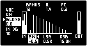
To access the VOCODER SCREEN push ALT + ◁ RIGHT SCREEN ENCODER / IN and use the ◁ RIGHT SCREEN ENCODER to select VOCODER. The screen provides an overview of the status of the VOCODER bands and all the parameters.
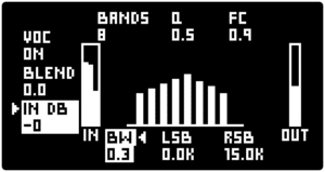
The IN meter is divided into 3 sections / bars. The left side band monitors the INPUT level, the middle band monitors the INPUT level post the [IN DB] boost, and the right side band monitors the VOICES level.
Push the ▷ LEFT SCREEN ENCODER to toggle between the parameters on the left side of the screen and turn the encoder to change the parameter values.
VOCODER Status [VOC] turns the VOCODER “ON” and “OFF”. When turned “OFF” the MOTOR Synth is in its normal operating mode and is outputting all VOICES. When turned “ON” all VOICES are mixed and passed through the VOCODER, and the INPUT signal’s spectrum is imprinted on the MOTOR Synth’s VOICES. If there is no audio going to the INPUT the VOCODER produces no output.
[BLEND] allows to blend in unaffected VOICES with the VOCODER output.
The INPUT Gain [IN DB] lets you boost the INPUT signal before it is used as a modulator for the VOCODER. It is possible to use a microphone plugged directly into the MOTOR SYNTH’S INPUT and use the [IN DB] parameter to boost the signal to the optimal level.
Push the ◁ RIGHT SCREEN ENCODER to toggle between the VOCODER BAND parameters in the top and bottom parts of the VOCODER SCREEN. Turn the encoder to change the parameter values.
The [BANDS] parameter adjusts the number of band pass filter BANDS that are used for vocoding. A maximum of 16 BANDS is possible and this number can be reduced down to 12, 8 or 4 BANDS. More BANDS produce higher definition results, especially when the human voice is being used as the modulator. However, a lower number of BANDS can produce a unique, yet less defined effect.
Note: The number of available BANDS is dependent on the available processing power reserved for MODULATION. If more than 3 parameters are modulated via the MODULATION section then the VOCODER is limited to 12 BANDS, and if more than 4 parameters are modulated then the VOCODER is limited to 8 BANDS.
The [FC] parameter (Carrier Graphic EQ Center Frequency ) determines the peak frequency of the carrier’s graphic equalizer and Gain of the Center Frequency [Q] determines the gain of the [FC]. These parameters allow shaping the overall spectral character of the carrier. In the example below the [FC] and [Q] parameters are used to boost the lower frequencies.
Note: For [FC] to have an effect, the [Q] parameter needs to be higher than 0.0.
Left Side Band Frequency [LSB] and Right Side Band Frequency [RSB] parameters determine the first and last band frequencies. All other bands are spread logarithmically evenly between these two frequencies.
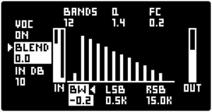
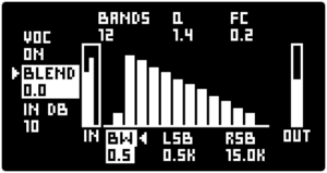
Band Width [BW] parameter determines the width of each single BAND. Greater separation between the BANDS will reduce the fidelity of the carrier signal and produce a more nasal-sounding effect. In the examples below the [BW] parameter is set to the highest and lowest values respectively.
The IN ENV FOLLOW section allows you to utilize the INPUT signal in several ways – to gate or duck the VOICES or to trigger the SEQUENCER or ARPEGGIATOR. Furthermore, it is possible to combine these applications.
To access the IN ENV FOLLOW SCREEN push ALT + ◁ RIGHT SCREEN ENCODER / IN and use the ◁ RIGHT SCREEN ENCODER to select IN GATE.
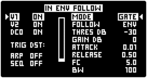
The ◁ RIGHT SCREEN ENCODER is used to to toggle and change the gating and ducking parameters. The ▷ LEFT SCREEN ENCODER is used to change the gating and ducking status for individual voices and to toggle SEQUENCER and ARPEGGIATOR triggering.
The [MODE] parameter can be set in one of three states: “OFF”, “DUCKING” and “GATE”. In the “OFF” mode the INPUT signal does not affect the VOICES. In the “DUCKING” and “GATE” modes the VOICES can be ducked and gated respectively by the incoming audio signal. The effect is applied to all VOICES that have the status set to “ON” with the ▷ LEFT SCREEN ENCODER.
Envelope Follower Mode [FOLLOW] determines how the INPUT signal’s envelope affects GATE and DUCKING. In the “ENV” mode the output volume is modulated in proportion to the amplitude of the INPUT signal, as long as it is above the [THRES DB] level. The INPUT signal’s rising and/or falling slopes can be adjusted by the [ATTACK] and/or [RELEASE] parameters respectively.
The “ONSET” Envelope Follower Mode [FOLLOW] does not create a full envelope based on the input signal, but rather produces a trigger from each transient that crosses the [THRES DB] level and the following GATE and DUCKING effect is fully determined by the values set with the [ATTACK] and [RELEASE] time parameters.
[GAIN DB] amplifies or attenuates the INPUT signal. This allows using various INPUT signal levels including microphones on low volume sound sources, such as the human voice.
A conditioning band-pass filter can be applied to the INPUT signal to dial in a specific frequency band for GATING and DUCKING. The INPUT Conditioning Bandpass Filter Cutoff [FC] determines the center frequency for the filter and the INPUT Filter Bandwidth [BW] parameter determines the width of the filter band , expressed as a percentage of the Input signal’s available frequency spectrum.
The [ARP] and [SEQ] parameters allow you to use the INPUT signal to trigger the ARPEGGIATOR and SEQUENCER, either separately or both together. When either of the parameters is set to “ON” the MOTOR Synth’s clock and the current MASTER TEMPO is detached from triggering them. Instead, triggers are generated each time the INPUT signal crosses the [THRES DB] level. Each trigger advances the ARPEGGIATOR and/or SEQUENCER to the next step.
Note: GATE / DUCKING and TRIGGER functions are independent and can be enabled simultaneously, but the INPUT signal conditioning parameters such as [THRES DB], [GAIN DB], [FC] and [BW] are shared.
To access the ROUTE SETTINGS SCREEN push ALT + ◁ RIGHT SCREEN ENCODER / IN and use the ◁ RIGHT SCREEN ENCODER to select ROUTE SET.
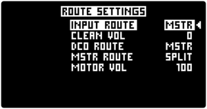
All parameters in the ROUTE SETTINGS SCREEN are controlled with the ◁ RIGHT SCREEN ENCODER.
[INPUT ROUTE] selects whether the INPUT signal is routed to the MASTER output or mixed with MOTOR VOICE 1 and/or VOICE 2 before the FILTER.
“MSTR” is the default setting in which the INPUT is mixed together with the MOTOR VOICES at the final output mixer. In the SPLIT ROUTE setting the DCO’s output is present in both output channels.
“V1” – the INPUT is mixed with MOTOR VOICE 1 before the FILTER of V1.
“V2” – the INPUT is mixed with MOTOR VOICE 2 before the FILTER of V2.
“V1+V2” – the INPUT is mixed both with MOTOR VOICE 1 and 2 before the FILTER of each MOTOR VOICE.
Note: When the INPUT is mixed with the MOTOR VOICES, it is passing through the voice's filter and final amp. This means that the final dynamic and harmonic sound characteristics are determined by the settings of the given MOTOR VOICE.
[CLEAN VOL] determines the level of INPUT signal sent to the output stage. This parameter does not affect the INPUT signal level for the VOCODER and GATE / SIDECHAIN engines.
[DCO ROUTE] selects different DCO routing options. This is a duplicate parameter to the one found in the DCO SCREEN.
“MSTR” is the default setting in which the DCO’s output is mixed together with the MOTOR VOICES at the final output mixer. In the SPLIT ROUTE setting the DCO’s output is present in both output channels.
“V1” – the DCO’s output is mixed with MOTOR VOICE 1 before the V1 FILTER. This allows the DCO to pass through its digital filter and then through the Analog multimode filter of MOTOR VOICE 1. This setting is most suitable for using the DCO as a tonal extension of a single MOTOR VOICE.
“V2” – the DCO’s output is mixed with MOTOR VOICE 2 before the V2 analog multimode FILTER.
“V1+V2” – the DCO’s output is mixed in with both MOTOR VOICES 1 and 2 before each MOTOR VOICE’s FILTER.
Note: When the DCO's output is mixed with the MOTOR VOICES, it is passing through the voice's filter and final amp. This means that the final dynamic and harmonic sound characteristics are determined by the given MOTOR VOICE.
[MSTR ROUTE] selects between two different MASTER OUTPUT configurations.
The “MIX L” setting mixes both MOTOR VOICES to the left output channel (TIP of a TRS cable). This is the appropriate setting to use when the MOTOR Synth is connected to a mono channel via a mono cable.
The “SPLIT” setting routes MOTOR VOICE 1 to the left output channel (TIP of a TRS cable) and MOTOR VOICE 2 to the right output channel (RING of a TRS cable). This allows you to send both of the MOTOR Synth’s channels into a different input channel, thus creating space for voice panning, or for individual signal path manipulation for each MOTOR VOICE.