MENU
The MODULATION section is a complex and detailed part of the MOTOR Synth. It is partly designed by following the main cornerstone of modular synthesis – the modulators are not configured to perform any specific tasks. Instead it is the user who completes the system by defining the input and output connections.
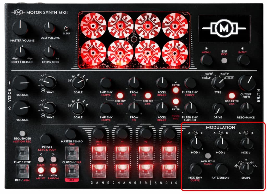
All of the parameters of each MODULATOR are organized in two screens – MOD SCREEN and MOD SHAPE screen. This section is organized in two parts accordingly.
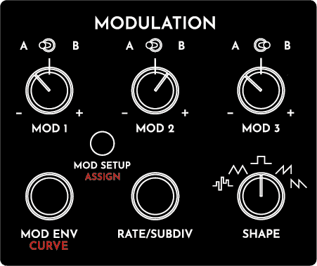
The MODULATORS are controlled with independent A/B Destination switches and MOD depth knobs. Other parameters are controlled with shared MOD ENV / CURVE, RATE/SUBDIV encoders and a rotary SHAPE switch. Furthermore, additional parameters are controlled with the ▷ LEFT & ◁ RIGHT SCREEN ENCODERS in the MOD SCREEN. To access the MOD SCREEN push the MOD SETUP button.
| PARAMETER | CONTROL | DESCRIPTION | VALUE RANGE |
|---|---|---|---|
| [MOD DEPTH A] | A/B switch in the “A” position + MOD knob | The modulation depth to Destination A. | From -100 (full depth inverted) through 0 to 100 (full depth) |
| [MOD DEPTH B] | A/B switch in the “B” position + MOD knob | The modulation depth to Destination B. | From -100 (full depth inverted) through 0 to 100 (full depth) |
| Destination A [A] | A/B switch in the “A” position + ALT + MOD SETUP / ASSIGN button | The modulated parameter. See the assignment instructions in the following section. | NA |
| Destination B [B] | A/B switch in the “B” position + ALT + MOD SETUP / ASSIGN button | The modulated parameter. See the assignment instructions in the following section. | NA |
| [MOD SHAPE] | SHAPE rotary switch | Modulation shape | ''STEP” Stepped shape;
“TRI” Triangle; “SQ” Squarewave; “SAW UP” Rising Sawtooh; “SAW DWN” Falling Sawtooth |
| [RATE] | RATE/SUBDIV encoder | Modulation rate in hertz or BPM | From 0 Hz to 32760.1 Hz |
| Subdivision [SUBDIV] | RATE/SUBDIV encoder | Subdivision or multiplication of the Clock Source [CLK SRC] frequency or BPM | Divisions from 1/2 to 1/32
Multiplications from 1/1 to 8/1 |
| Clock Source [CLK SRC] | ▷ LEFT SCREEN ENCODER | The clock source for [RATE] | “INT” Internal arbitrary frequency of the given MODULATOR;
“MOD 1/2/3” The [RATE] of another MODULATOR; “BPM” Master tempo; “NOTE” the frequency of the last note played |
| Phase Reset [PHASE RST] | ▷ LEFT SCREEN ENCODER | Toggle of MODULATOR phase reset on each new note played | “OFF” No reset;
“ON” MODULATOR phase is reset with each new note played. |
| PARAMETER | CONTROL | DESCRIPTION | VALUE RANGE | ||||
|---|---|---|---|---|---|---|---|
|
[MOD DEPTH A] |
A/B switch in the “A” position + MOD knob |
The modulation depth to Destination A. |
From -100 (full depth inverted) through 0 to 100 (full depth) |
||||
| PARAMETER | CONTROL | DESCRIPTION | VALUE RANGE | ||||
|---|---|---|---|---|---|---|---|
|
[MOD DEPTH B] |
A/B switch in the “B” position + MOD knob |
The modulation depth to Destination B. |
From -100 (full depth inverted) through 0 to 100 (full depth) |
||||
| PARAMETER | CONTROL | DESCRIPTION | VALUE RANGE | ||||
|---|---|---|---|---|---|---|---|
|
Destination A [A] |
A/B switch in the “A” position + ALT + MOD SETUP / ASSIGN button |
The modulated parameter. See the assignment instructions in the following section. |
NA |
||||
| PARAMETER | CONTROL | DESCRIPTION | VALUE RANGE | ||||
|---|---|---|---|---|---|---|---|
|
Destination B [B] |
A/B switch in the “B” position + ALT + MOD SETUP / ASSIGN button |
The modulated parameter. See the assignment instructions in the following section. |
NA |
||||
| PARAMETER | CONTROL | DESCRIPTION | VALUE RANGE | ||||
|---|---|---|---|---|---|---|---|
|
[MOD SHAPE] |
SHAPE rotary switch |
Modulation shape |
”STEP” Stepped shape; |
||||
| PARAMETER | CONTROL | DESCRIPTION | VALUE RANGE | ||||
|---|---|---|---|---|---|---|---|
|
[RATE] |
RATE/SUBDIV encoder |
Modulation rate in hertz or BPM |
From 0 Hz to 32760.1 Hz |
||||
| PARAMETER | CONTROL | DESCRIPTION | VALUE RANGE | ||||
|---|---|---|---|---|---|---|---|
|
Subdivision [SUBDIV] |
RATE/SUBDIV encoder |
Subdivision or multiplication of the Clock Source [CLK SRC] frequency or BPM |
Divisions from 1/2 to 1/32; |
||||
| PARAMETER | CONTROL | DESCRIPTION | VALUE RANGE | ||||
|---|---|---|---|---|---|---|---|
|
Clock Source [CLK SRC] |
▷ LEFT SCREEN ENCODER |
The clock source for [RATE] |
“INT” Internal arbitrary frequency of the given MODULATOR; |
||||
| PARAMETER | CONTROL | DESCRIPTION | VALUE RANGE | ||||
|---|---|---|---|---|---|---|---|
|
Phase Reset [PHASE RST] |
▷ LEFT SCREEN ENCODER |
Toggle of MODULATOR phase reset on each new note played |
“OFF” No reset; |
||||
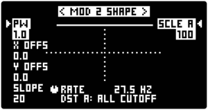
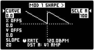
Each MODULATOR has its main [MOD SHAPE] parameter controlled by the SHAPE rotary switch. However, the shape can be further sculpted with a set of SHAPE parameters in the MOD SHAPE SCREEN (listed below) controlled with the ▷ LEFT &
◁ RIGHT SCREEN ENCODERS. To access the MOD SHAPE SCREEN, enter the MOD SCREEN by pushing the MOD SETUP button. To access the MOD SHAPE SCREEN, first enter the MOD SCREEN by pushing the MOD SETUP button and then press the ◁ RIGHT SCREEN ENCODER labelled “SHAPE CTRL”.
This list contains an overview of all parameters in this section. For further information refer to the Instructions sub-section. The availability of several parameters is dependent on the main [SHAPE] selection with the SHAPE rotary switch. This is indicated in the Description column.
| PARAMETER | CONTROL | DESCRIPTION | VALUE RANGE |
|---|---|---|---|
| [CURVE] | ▷ LEFT SCREEN ENCODER | The curve of all sloped [MOD SHAPES]. Not available for ''STEP” and “SQ” shapes. | From -1 (exponential) through 0 (linear) to 1 (inverse exponential) |
| Pulse Width [PW] | ▷ LEFT SCREEN ENCODER | The pulse width of the “SQ” Squarewave shape. Not available for other shapes. | From -1 (0% duty cycle) through 0 (50% duty cycle) to 1 (100% duty cycle) |
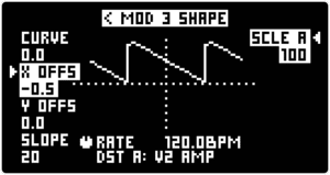
| X-axis Offset [X OFFS] | ▷ LEFT SCREEN ENCODER | Waveform offset on the X-axis, or in other words waveform phase offset. | From -0.5 (-90°) through 0 (0°) to 0.5 (90°) |
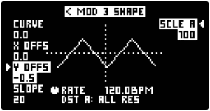
| Y-axis Offset [Y OFFS] | ▷ LEFT SCREEN ENCODER | Waveform offset on the Y-axis or in other words waveform output offset. | From -0.5 through 0 to 0.5 |
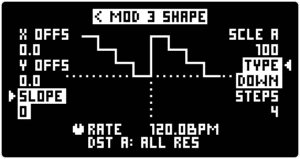
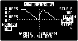
| [SLOPE] | ▷ LEFT SCREEN ENCODER | Slew amount | From 0 to 100 |
| [SCALE A] | A/B switch in the “A” position +◁ RIGHT SCREEN ENCODER | The maximum possible MODULATOR for Destination A | From 0 to 100 |
| [SCALE B] | A/B switch in the “B” position + ◁ RIGHT SCREEN ENCODER | The maximum possible MODULATOR for Destination B | From 0 to 100 |
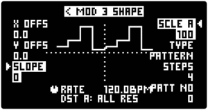
| Stepped Type [TYPE] | ◁ RIGHT SCREEN ENCODER | Stepped shape “STEP” type | “UP” rising stepped waveform;
“DOWN” falling stepped waveform; “NOISE”; “PATTERN” predefined stepped pattern; “RND” random stepped waveform |
| [STEPS] | ◁ RIGHT SCREEN ENCODER | The number of steps within one waveform cycle. Not available on “NOISE” | From 2 to 8 |
| Pattern Number [PAT NO] | ◁ RIGHT SCREEN ENCODER | The predefined pattern number. Only available for “PATTERN” | From 0 to 15;
No 15 is a randomly generated and repeated pattern. |
| Noise Grain [GRAIN] | ◁ RIGHT SCREEN ENCODER | Sample and hold of “NOISE”. Only available for “NOISE” | From 0 to 1 |
| PARAMETER | CONTROL | DESCRIPTION | VALUE RANGE |
|---|---|---|---|
| [CURVE] | ▶ LEFT SCREEN ENCODER | The curve of all sloped [MOD SHAPES]. Not available for ''STEP” and “SQ” shapes. | From -1 (exponential) through 0 (linear) to 1 (inverse exponential) |
| Pulse Width [PW] | ▶ LEFT SCREEN ENCODER | The pulse width of the “SQ” Squarewave shape. Not available for other shapes. | From -1 (0% duty cycle) through 0 (50% duty cycle) to 1 (100% duty cycle) |
| X-axis Offset [X OFFS] | ▶ LEFT SCREEN ENCODER | Waveform offset on the X-axis, or in other words waveform phase offset. | From -0.5 (-90°) through 0 (0°) to 0.5 (90°) |
| Y-axis Offset [Y OFFS] | ▶ LEFT SCREEN ENCODER | Waveform offset on the Y-axis or in other words waveform output offset. | From -0.5 through 0 to 0.5 |
| [SLOPE] | ▶ LEFT SCREEN ENCODER | Slew amount | From 0 to 100 |
| [SCALE A] | A/B switch in the “A” position + ◀ RIGHT SCREEN ENCODER | The maximum possible MODULATOR for Destination A | From 0 to 100 |
| [SCALE B] | A/B switch in the “B” position + ◀ RIGHT SCREEN ENCODER | The maximum possible MODULATOR for Destination B | From 0 to 100 |
| Stepped Type [TYPE] | ▶ RIGHT SCREEN ENCODER | Stepped shape “STEP” type | “UP” rising stepped waveform; “DOWN” falling stepped waveform; “NOISE”; “PATTERN” predefined stepped pattern; “RND” random stepped waveform |
| [STEPS] | ▶ RIGHT SCREEN ENCODER | The number of steps within one waveform cycle. Not available on “NOISE” | From 2 to 8 |
| Pattern Number [PAT NO] | ▶ RIGHT SCREEN ENCODER | The predefined pattern number. Only available for “PATTERN” | From 0 to 15. No 15 is a randomly generated and repeated pattern. |
| Noise Grain [GRAIN] | ▶ RIGHT SCREEN ENCODER | Sample and hold of “NOISE”. Only available for “NOISE” | From 0 to 1 |
| PARAMETER | CONTROL | DESCRIPTION | VALUE RANGE | ||||
|---|---|---|---|---|---|---|---|
|
[CURVE] |
▷ LEFT SCREEN ENCODER |
The curve of all sloped [MOD SHAPES]; |
From -1 (exponential) through 0 (linear) to 1 (inverse exponential) |
||||
| PARAMETER | CONTROL | DESCRIPTION | VALUE RANGE | ||||
|---|---|---|---|---|---|---|---|
|
Pulse Width [PW] |
▷ LEFT SCREEN ENCODER |
The pulse width of the “SQ” Squarewave shape; |
From -1 (0% duty cycle) through 0 (50% duty cycle) to 1 (100% duty cycle) |
||||
| PARAMETER | CONTROL | DESCRIPTION | VALUE RANGE | ||||
|---|---|---|---|---|---|---|---|
|
X-axis Offset [X OFFS] |
▷ LEFT SCREEN ENCODER |
Waveform offset on the X-axis, or in other words waveform phase offset |
From -0.5 (-90°) through 0 (0°) to 0.5 (90°) |
||||
| PARAMETER | CONTROL | DESCRIPTION | VALUE RANGE | ||||
|---|---|---|---|---|---|---|---|
|
Y-axis Offset [Y OFFS] |
▷ LEFT SCREEN ENCODER |
Waveform offset on the Y-axis or in other words waveform output offset |
From -0.5 through 0 to 0.5 |
||||
| PARAMETER | CONTROL | DESCRIPTION | VALUE RANGE | ||||
|---|---|---|---|---|---|---|---|
|
[SLOPE] |
▷ LEFT SCREEN ENCODER |
Slew amount |
From 0 to 100 |
||||
| PARAMETER | CONTROL | DESCRIPTION | VALUE RANGE | ||||
|---|---|---|---|---|---|---|---|
|
[SCALE A] |
A/B switch in the “A” position + ◁ RIGHT SCREEN ENCODER |
The maximum possible MODULATOR for Destination A |
From 0 to 100 |
||||
| PARAMETER | CONTROL | DESCRIPTION | VALUE RANGE | ||||
|---|---|---|---|---|---|---|---|
|
[SCALE B] |
A/B switch in the “B” position + ◁ RIGHT SCREEN ENCODER |
The maximum possible MODULATOR for Destination B |
From 0 to 100 |
||||
| PARAMETER | CONTROL | DESCRIPTION | VALUE RANGE | ||||
|---|---|---|---|---|---|---|---|
|
Stepped Type [TYPE] |
◁ RIGHT SCREEN ENCODER |
Stepped shape “STEP” type |
“UP” rising stepped waveform; |
||||
| PARAMETER | CONTROL | DESCRIPTION | VALUE RANGE | ||||
|---|---|---|---|---|---|---|---|
|
[STEPS] |
◁ RIGHT SCREEN ENCODER |
The number of steps within one waveform cycle. Not available on “NOISE” |
From 2 to 8 |
||||
| PARAMETER | CONTROL | DESCRIPTION | VALUE RANGE | ||||
|---|---|---|---|---|---|---|---|
|
Pattern Number [PAT NO] |
◁ RIGHT SCREEN ENCODER |
The predefined pattern number. Only available for “PATTERN” |
From 0 to 15. No 15 is a randomly generated and repeated pattern. |
||||
| PARAMETER | CONTROL | DESCRIPTION | VALUE RANGE | ||||
|---|---|---|---|---|---|---|---|
|
Noise Grain [GRAIN] |
◁ RIGHT SCREEN ENCODER |
Sample and hold of “NOISE”. Only available for “NOISE” |
From 0 to 1 |
||||
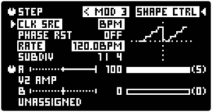
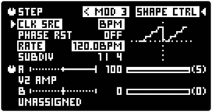
Push the MOD SETUP button to toggle between the two main MODULATION screens: the MOD SCREEN and MOD SETUP SCREEN.
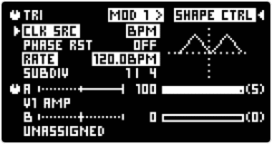
The MOD SCREEN provides access to all MODULATOR parameters of a single MODULATOR. Navigate between MODULATORS by using the < / >arrow buttons as indicated by the “< >” symbols at the top of the MOD SCREEN. Alternatively turn the MOD knob of the desired MODULATOR and the respective MOD SCREEN will be displayed.
To switch between each MODULATOR’s two Mod Destinations [A] and [B] use the A/B switch above the respective MOD knob. The selected Destination is indicated by the knob symbol in the MOD SCREEN. In the picture above it is set to MOD Destination slot [A] – V2 ALL CUTOFF.
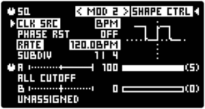
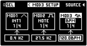
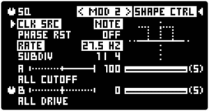
The MOD SETUP SCREEN provides an overview of all three MODULATORS and quick access to their Clock Source [CLK SRC] and Subdivision [SUBDIV] parameters. Push the < / > arrow buttons or turn the ▷ LEFT SCREEN ENCODER to toggle between MODULATORS. Push the ◁ RIGHT SCREEN ENCODER to toggle between each Modulator’s Clock Source [CLK SRC] and turn the ◁ RIGHT SCREEN ENCODER to change the [CLK SRC] for the highlighted MODULATOR.
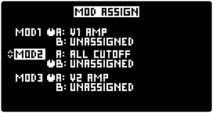
In the FACTORY INIT preset MOD 1A is assigned to Amplitude of MOTOR VOICE 1 [V1 AMP], MOD2 A is assigned to All FILTER Cutoffs [ALL CUTOFF] and MOD 3A is assigned to Amplitude of MOTOR VOICE 2. The B slots of all MODULATORS are “UNASSIGNED”.
Push the ALT + MOD SETUP / ASSIGN button to confirm the selected MOD SLOT and the MOD ASSIGN SCREEN will close. A pop-up “TURN TO ASSIGN MOD 2A” will appear which indicates that the MOD 2A slot is armed.
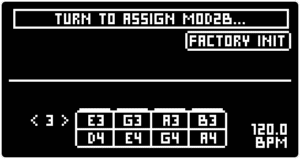
Adjust any knob or switch on the MOTOR Synth’s front panel or any parameter via the SCREEN ENCODERS to ASSIGN it as the destination for MOD 2B.
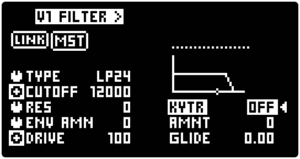
For example, if the DRIVE knob is now turned the [DRIVE] parameter of the selected filter will be assigned to the armed MODULATOR. Or like in the example below, if the FILTERS are LINKED then the [DRIVE] parameter of all FILTERS will be assigned to the MODULATOR. This is indicated by a new pop-up on the screen, and the MOD SETUP / ASSIGN button will repeatedly blink.
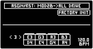
The final step in the MOD ASSIGN process is to confirm the assignment by pushing the ALT + MOD SETUP / ASSIGN button one last time. The MOD SETUP / ASSIGN button will stop blinking and the MODULATOR will be assigned to the parameter.
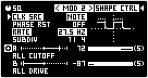
Push the MOD SETUP button to open the MOD SETUP SCREEN, the assigned parameter name displayed under the [MOD DEPTH] slot [B] indicator.

Any parameter in the MOTOR Synth that is assigned as an active MOD DESTINATION is indicated by this target symbol:
To exit the MOD ASSIGN mode without assigning push the ALT + > / RESET button at any time.
Note: The last confirmation step during the mod-assign process is introduced for two reasons. First, to avoid accidental parameter assignment. If the modulator is assigned to an undesired parameter, simply turn another knob or use another switch to assign it to the desired parameter instead. Then perform the last confirmation step.The second reason is to enable navigation through various screens to access parameters that are controlled with SCREEN ENCODERS instead of dedicated knobs on the front pane, for example DCO parameters.. The MOD ASSIGN process will remain active while navigating to the desired parameter and until the final desired assignment destination is confirmed.
Note: The global SYSTEM settings allow for two specific behaviors of knobs and switches during the MOD ASSIGN process which requires the user to turn the knob of the desired parameter. One of the optional behaviors freezes the parameter so that it is not changed during the MOD ASSIGN process. The other option is for the parameter to follow the knob movement also during the MOD ASSIGN process. Refer to the SETTINGS MENU section for more information.
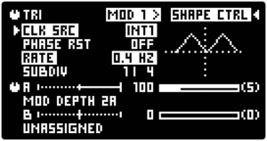
Tip: The MODULATORS can be assigned to nearly any parameter on the MOTOR Synth including parameters of other MODULATORS. This allows to create cross-modulation between them. For example, to assign MOD 1A to the [DEPTH] of MOD 2A push the ALT + MOD SETUP / ASSIGN button. Turn the MOD1 knob and press ALT + MOD SETUP / ASSIGN to confirm and arm the MOD 1A slot. Now turn the MOD2 depth knob to assign it to MOD 1A. Push the ALT + MOD SETUP / ASSIGN button to confirm the assignment. Use the < & > buttons to navigate between the MODULATORS. The MOD 1A is modulating the depth of MOD 2A which is modulating the [CUTOFF] of linked FILTERS.

Turn the ▷ LEFT SCREEN ENCODER to select the Clock Source [CLK SRC]. The [CLK SRC] is used to determine the frequency of the MODULATOR which can be further divided or multiplied with the Subdivision [SUBDIV] parameter. The table below lists the possible [CLK SRC] options and typical applications.
| [CLK SRC] | Explanation | Application |
|---|---|---|
| “INT” | Internal arbitrary frequency of the given MODULATOR | The internal arbitrary frequency is useful when imitating classic low frequency oscillators with a simple frequency control. This clock source is fully independent of the master tempo and the performance. |
| “MOD 1/2/3” | The [RATE] of another MODULATOR | Using the frequency of another MODULATOR allows the same frequency or division or multiplication of it. Changing the frequency of the source MODULATOR will immediately affect the target MODULATOR as well. This allows the creation of rhythmically related MODULATORS and simultaneous control over several MODULATORS by changing the frequency of a single MODULATOR. |
| “BPM” | Master tempo | Using the Master tempo as clock source allows the creation of MODULATORS that are rhythmically related to the Master tempo. The typical application is for rhythmic performances with the ARPEGIATOR and SEQUENCER. However, if the synthesizer is freely performed “off the grid” the Master tempo still allows control of the MODULATORS that use it as “CLK SRC”. This means that TAP TEMPO can be used to quickly change the frequency of the MODULATORS. |
| “NOTE” | The frequency of the last note played | Using the frequency of the last note played allows to create MODULATORS rhythmically related to the pitch of the performance. A large division of the Note’s frequency using the [SUBDIV] parameter will provide sub-audio frequency for the MODULATOR. However a small division of the note’s frequency or the exact frequency can be used for audio-rate modulation. |
| [CLK SRC] | Explanation | Application | |||
|---|---|---|---|---|---|
|
“INT” |
Internal arbitrary frequency of the given MODULATOR |
The internal arbitrary frequency is useful when imitating classic low frequency oscillators with a simple frequency control. This clock source is fully independent of the master tempo and the performance. |
|||
| [CLK SRC] | Explanation | Application | |||
|---|---|---|---|---|---|
|
“MOD 1/2/3” |
The [RATE] of another MODULATOR |
Using the frequency of another MODULATOR allows the same frequency or division or multiplication of it. Changing the frequency of the source MODULATOR will immediately affect the target MODULATOR as well. This allows the creation of rhythmically related MODULATORS and simultaneous control over several MODULATORS by changing the frequency of a single MODULATOR. |
|||
| [CLK SRC] | Explanation | Application | |||
|---|---|---|---|---|---|
|
“BPM” |
Master tempo |
Using the Master tempo as clock source allows the creation of MODULATORS that are rhythmically related to the Master tempo. The typical application is for rhythmic performances with the ARPEGIATOR and SEQUENCER. However, if the synthesizer is freely performed “off the grid” the Master tempo still allows control of the MODULATORS that use it as “CLK SRC”. This means that TAP TEMPO can be used to quickly change the frequency of the MODULATORS. |
|||
| [CLK SRC] | Explanation | Application | |||
|---|---|---|---|---|---|
|
“NOTE” |
The frequency of the last note played |
Using the frequency of the last note played allows to create MODULATORS rhythmically related to the pitch of the performance. A large division of the Note’s frequency using the [SUBDIV] parameter will provide sub-audio frequency for the MODULATOR. However a small division of the note’s frequency or the exact frequency can be used for audio-rate modulation. |
|||
Note: The Phase Reset [PHASE RST] function is also active when the [CLK SRC] is set to “BPM” in which case only the frequency of the MODULATOR is determined by the Master Tempo but not the phase.
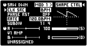
The [SHAPE] parameter controlled with the SHAPE knob determines the basic MODULATOR waveform. It can be further sculpted in the dedicated MOD SHAPE SCREEN.
Push the MOD SETUP button to enter the MOD SCREEN, navigate to the desired MODULATOR and then push the ◁ RIGHT SCREEN ENCODER [SHAPE CTRL] to enter the MOD SHAPE SCREEN.
There are separate shape parameters available for different shape types [SHAPE]. All parameters are shared between both destinations of a single MODULATOR except for the Output Scale [SCALE] which is independent for each destination. All parameters are controlled with the ▷ LEFT & ◁ RIGHT SCREEN ENCODERS. Push the SCREEN ENCODERS to toggle between different SHAPE parameters and turn the SCREEN ENCODERS to change the parameter values.
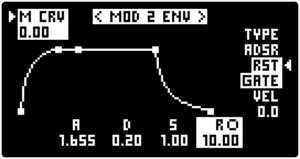
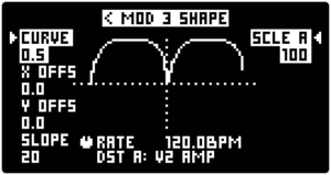
[CURVE]
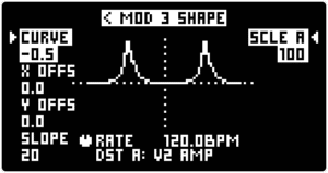
The [CURVE] parameter is available for all sloped [SHAPES]. By default the slopes are linear and are adjustable to be exponential or inverse exponential. Changing the [CURVE] of the modulation drastically alters the sound without adjusting the [RATE] and [DEPTH] of the modulation. In the examples below the Triangle “TRI” shape is shown as an exponential [CURVE] and an inverse exponential [CURVE] respectively, thus showcasing the power of the [CURVE] parameter.
Pulse Width [PW]
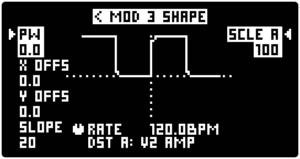
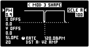
The Pulse Width [PW] parameter is available only for the Squarewave “SQ” [SHAPE]. The width is adjustable from a 0% to a 100% duty cycle. A 100% Pulse Width [PW] allows to create a flat offset for the destination parameter, with the [DEPTH] parameter functioning as an offset value in this case.
X-axis Offset [X OFFS]
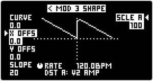
The X-axis Offset [X OFFS] can also be described as a waveform phase offset. The effect of this parameter is heard when the MODULATORS are synchronized to some other event. For example, when [PHASE RST] is set to “ON” the [X OFFS] determines the starting point of the waveform with each new note played.
Y-axis Offset [Y OFFS]
The Y-axis Offset [Y OFFS] can also be described as a waveform output offset. The polarity of modulation greatly alters the outcoming sound. For example, if the shape is fully in the positive region, then with positive [DEPTH] values the destination parameter will be modulated upwards from the parameter’s set value. If the [Y OFFS] places the waveform in both positive and negative range crossing the 0, then the destination waveform will be modulated both upwards and downwards from the set value.
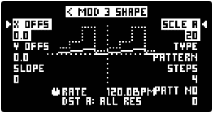
[SLOPE]
[SLOPE] is the slew amount applied to the [SHAPE]. This allows to smooth out random and stepped waveforms such as in the example below, as well as squarewave and other waveforms with hard edges.
[SCALE A] & [SCALE B]
The [SCALE] parameter is individual for each MOD DESTINATION. Use the A/B switch to toggle between [SCALE A] and [SCALE B]. This parameter allows to dial in the maximum possible MODULATION output with the MOD depth knob in both the maximum positive and negative positions. This parameter is useful when a full modulation depth of the destination parameter is undesirable. In this case the [SCALE] parameter allows to fine-tune the range of the MOD knob so that the full movement of the knob provides useful modulation depths.
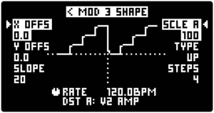
Stepped shape “STEP” parameters: Stepped Type [TYPE], [STEPS], Pattern Number [PAT NO] and Noise Grain [GRAIN].
These four parameters are only available for the “STEP” [SHAPE].
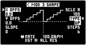
Stepped Type [TYPE] parameter toggles between several distinct stepped voltage types: “UP” rising stepped waveform, “DOWN” falling stepped waveform, “NOISE”, “PATTERN” predefined stepped pattern, “RND” random stepped waveform.
The [STEPS] parameter determines the number of steps within one period of the waveform. From 2 to 8 are possible.
The [PAT NO] parameter scrolls through several predefined patterns when [TYPE] is set to “PATTERN”. Slots 0-14 are predefined patterns but slot 15 is a randomly generated and repeated pattern. The slot 15 is randomly generated each time it is selected.
Noise Grain [GRAIN] is the noise sample rate reduction parameter.
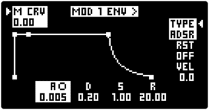
Tip: There is is a hidden technique how the MOD ENVELOPE can be applied to any other parameter, that does not have a dedicated envelope generator. The technique involves assigning a MODULATOR to the desired parameter and bypassing the MODULATOR itself so that the parameter can be modulated by the MOD ENVELOPE. Choose a MODULATOR and ASSIGN it to the desired parameter. Set the [MOD SHAPE] to Squarewave “SQ”. Enter the MOD SHAPE SCREEN and set the Pulse Width [PW] to 100. This produces a flat offset. As the MODULATOR output is modulated by the MOD ENVELOPE it is virtually bypassed and the MOD ENVELOPE modulates the destination parameter. Furthermore, the MOD knob functions as an envelope amount in this setup.