MENU
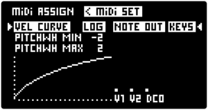
The MIDI ASSIGN section gives control over MIDI mod wheel, channel pressure assignments as well as settings for MIDI velocity curve and pitchwheel depth.
For general MIDI settings see the SETTINGS MENU / MIDI SCREEN section.
To access the MIDI ASSIGN SCREEN press ALT + ◁ RIGHT SCREEN ENCODER / INPUT and then use the ◁ RIGHT SCREEN ENCODER to select MIDI ASSIGN and press to enter.
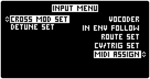
Use the < / > arrow buttons to navigate between MIDI ASSIGN and MIDI SET SCREENS.
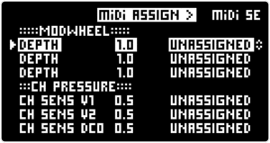
Press the ◁ RIGHT SCREEN ENCODER to start the assignment process for the selected slot. The “UNASSIGNED ” text will change to “TURN KNOB” and pop-up will appear “TURN TO ASSIGN MODWHEEL SLOT1 ” which indicates that the mod wheel slot 1 is armed.
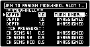
Similarly to the MODULATOR assignment process it is possible to turn any knob or encoder on the front panel or navigate to other screens and adjust any parameter with the SCREEN ENCODERS to assign it as the destination for the selected mod wheel slot.
For example, if the DRIFT | DETUNE knob is now turned the [DRIFT / DETUNE] parameters will be assigned to the armed modwheel slot. This is indicated by a new pop-up on the screen “MODWHEEL SLOT 1->DRIFTDETUNE”, and the MOD SETUP / ASSIGN button will repeatedly blink.
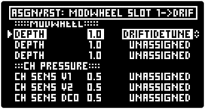
To confirm the assignment press ALT + MOD SETUP / ASSIGN button in the MODULATION section. Alternatively, if the MIDI ASSIGN SCREEN is still active, press the ◁RIGHT SCREEN ENCODER to confirm the assignment.
To cancel the assignment process press ALT + > / RESET at any time.
Any parameter in the MOTOR Synth that is assigned as an active mod wheel or channel pressure destination is indicated by the M and CP symbols respectively.
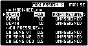
The MIDI ASSIGN SCREEN also allows to dial in the maximum mod wheel and channel pressure depth for each individual assignment slot.
Push the ▷ LEFT SCREEN ENCODER to jump between the assignment slots and turn the encoder to set the maximum modulation depth from the parameter’s actual value. Both positive and negative modulation is possible.
Note: The SETTINGS MENU / PARAMETER SETTINGS AND BRIGHTNESS SCREEN allow for two specific behaviors of knobs and switches during the mod wheel and channel pressure assignment process which requires the user to turn the knob of the desired parameter. One of the optional behaviors freezes the parameter so that it is not changed during the assignment process. The other option is for the parameter to follow the knob movement also during the assignment process.
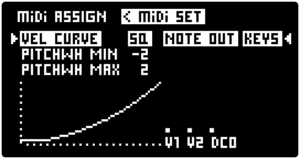
The [PITCHWH MIN / MAX] parameters set the minimum and maximum pitch modulation depth for MIDI pitch wheel in semitones. Intervals up to one octave up and down are possible.
Turn the ◁ RIGHT SCREEN ENCODER to set the [NOTE OUT] parameter which determines what generates the MIDI note output: “KEYS” – MIDI notes generated by the KEYPAD, “SEQ” – MIDI notes generated by the SEQUENCER.