fbpx

EXPRESS SHIPPING WORLDWIDE - DIRECT FROM MANUFACTURER

gca logo new page

18 CV AND TRIGGER INPUTS

18.1 Description

The MOTOR Synth features 3 control voltage and 3 trigger inputs on the back panel. These are labeled CV1, CV2, CV3, TRIG1, TRIG2 and TRIG3. Similar to the MODULATION section, the CV inputs can be assigned to nearly any parameter on the MOTOR Synth and the TRIGGERS have several predefined destinations. The CV input range is from -10V to +10V and all CV inputs can be individually attenuated and inverted. The TRIGGER inputs accept triggers and gates crossing 2.5V.

18.2 Instructions

CV and TRIGGERS are managed in the CV ASSIGN SCREEN and CV ATTENUATE SCREEN. Push ALT + ◁ RIGHT SCREEN ENCODER / IN and choose CV/TRIG SET. Use the < / > arrow buttons to navigate between both screens. 

18.2.1 CV/TRIG MODES

There are several [CV/TRIG MODES] that determine the CV and TRIGGER assignment.

“OFF
CV and TRIG inputs are disabled even if there are parameters assigned

“PARAM”
CV1 – PARAM (assigned parameter modulation mode)
CV2 – PARAM
CV3 – PARAM
TRIG1 – OFF
TRIG2 – CLK RST (MASTER TEMPO reset)
TRIG3 – CLK (MASTER TEMPO sync)

“1V/OCT ALL”
CV1 – 1V/OCT ALL (pitch of all VOICES)
CV2 – PARAM
CV3 – PARAM
TRIG1 – GATE ALL (gate of all VOICES)
TRIG2 – CLK RST
TRIG3 – CLK

“1V/OCT VX”
CV1 – 1V/OCT V1
CV2 – 1V/OCT V2
CV3 – 1V/OCT DCO
TRIG1 – GATE V1
TRIG2 – GATE V2
TRIG3 – GATE DCO

“1V/OCT V1/2”
CV1 – 1V/OCT V1
CV2 – 1V/OCT V2
CV3 – PARAM
TRIG1 – GATE V1
TRIG2 – GATE V2
TRIG3 – CLK

“TRIG ARP/SEQ”
CV1 – 1V/OCT ALL
CV2 – PARAM
CV3 – PARAM
TRIG1 – GATE ALL
TRIG2 – TRIG A/S (trigger ARPEGGIATOR and SEQUENCER simultaneously)
TRIG3 – CLK (in this case only modulation and BPM detection is synced to external clock via TRIG3)

“TRIG ARP”
CV1 – 1V/OCT ALL
CV2 – PARAM
CV3 – PARAM
TRIG1 – GATE ALL
TRIG2 – TRIG ARP
TRIG3 – CLK  (in this case only modulation and BPM detection is synced to external clock via TRIG3)

“TRIG SEQ”
CV1 – 1V/OCT ALL
CV2 – PARAM
CV3 – PARAM
TRIG1 – GATE ALL
TRIG2 – TRIG SEQ
TRIG3 – CLK  (in this case only modulation and BPM detection is synced to external clock via TRIG3)

IN THIS SECTION

18.2.2 CV assignment

If a CV slot is set to “PARAM” then it can be used to modulate any parameter it is assigned to.

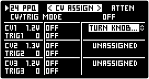
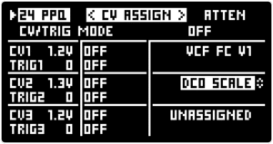
To assign a parameter select a PARAM assign slot by turning the  RIGHT SCREEN ENCODER. Press the encoder to start the assignment process. Adjust any knob/switch on the MOTOR Synth’s front panel or any parameter in all individual SCREENS via the SCREEN ENCODERS to ASSIGN it as the destination. The last adjusted parameter will be assigned to the CV input. The assignment needs to be confirmed by pressing the ALT + MOD SETUP / ASSIGN in the MODULATION section. If the assignment was done only by turning a knob or encoder on the front panel without exiting the CV ASSIGN SCREEN the assignment can also be confirmed by pressing the  RIGHT SCREEN ENCODER.

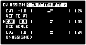
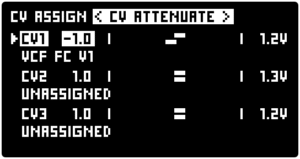
The confirmed assigned parameter is displayed on the right from the CV slot.

To cancel the assignment process at any time press ALT + > / RESET.

To clear the assignment for the selected CV slot press ALT + < / CLEAR.

18.2.3 CV attenuation

All 3 CV inputs can be attenuated and inverted in the CV ASSIGN SCREEN.

Press the > arrow button to navigate to the CV ATTENUATE SCREEN and push the  LEFT SCREEN ENCODER to toggle between the CV slots and turn the encoder to attenuate and/or invert the incoming CV. The positive values attenuate the CV and the negative values attenuate and invert it.

Curious?

Leave your email to receive news and subscriber-only deals!