MENU
One of the main new features in the MOTOR Synth MKII is the added third DIGITAL VOICE (DCO).
The DCO is a powerful additional tool for extending the tonal variety, precision and range of the motor oscillators. The DCO is based on a proprietary virtual-analog oscillator and noise engine. The waveshaping options offered include wavefolding, pulse-width modulation and hard sync to MOTOR VOICE 1 or 2.
The DIGITAL VOICE follows a similar signal path as the MOTOR VOICES 1 & 2. It consists of 4 digital oscillators and an independent amp for each oscillator. All 4 oscillators are mixed together and sent into one virtual-analog filter. The differences in the DCO’s signal path are in the output routing options. The DCO can be routed to the main output mixer, or it can be summed together with one of the MOTOR VOICES before the analog FILTER of the given voice. This allows the use of the DCO as a supplement to a MOTOR VOICE – for adding a sub-octave, upper harmonics, transients, noise etc.
Apart from the added waveshaping options the DCO has the same set of features and parameters as the MOTOR VOICES, but the access to these parameters is different.
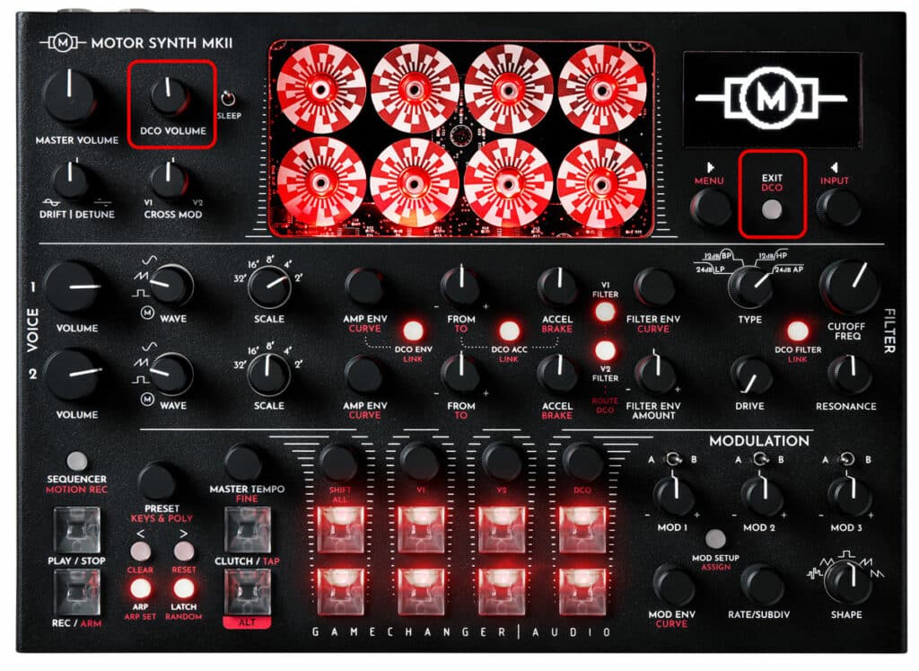
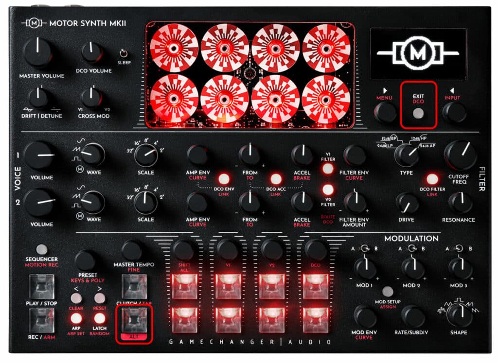
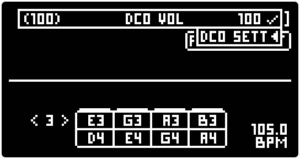
The DCO is controlled with a dedicated DCO VOLUME knob in the MASTER section on the front panel. Additional wave-shaping parameters can be adjusted in the DCO SCREEN with the ▷ LEFT & ◁ RIGHT SCREEN ENCODERS. To access the DCO screen push the ALT + EXIT / DCO button below the screen.
This list contains an overview of all parameters in this section. For further information refer to the Instructions sub-section. This list does not include the DCO AMP ENVELOPE and DCO ACCELERATION / BRAKE parameters that are the same as for the MOTOR VOICE AMP ENVELOPE.
| PARAMETER | CONTROL | DESCRIPTION | VALUE RANGE |
|---|---|---|---|
| [VOLUME] | DCO VOLUME knob | The volume level of the DCO | From 0 to 100 |
| [SCALE] | ◁ RIGHT SCREEN ENCODER | Scale (octave) select | 32' / 16' / 8' / 4' / 2 ' |
| Waveform [WAVE] | ◁ RIGHT SCREEN ENCODER | Waveshape output select | “PULSE”;
“SAW”; Triangle “TRI”; “SINE”; “NOISE” |
| [ROUTE TO] | ◁ RIGHT SCREEN ENCODER | The DCO output routing setting | “MSTR” Master output;
“V1” Mix with MOTOR VOICE 1; “V2” Mix with MOTOR VOICE 2; “V1+V2” Mix with MOTOR VOICES 1 & 2 |
| Motor Volume [MOTOR VOL] | ◁ RIGHT SCREEN ENCODER | Motor volume | From 0 to 100 |
| Pulse Width [PULSE W] | ▷ LEFT SCREEN ENCODER | Manual pulse width control in percentage of a period.* | From 0 to 100 |
| Wavefolding [FOLD] | ▷ LEFT SCREEN ENCODER | Wavefolding amount.* | From 0 to 100 |
| Hard Sync [HSYNC] | ▷ LEFT SCREEN ENCODER | Hard sync status.* | “OFF” - not hard synced;
“ON” - hard synced to a MOTOR VOICE |
| Hard Sync Input [TO] | ▷ LEFT SCREEN ENCODER | The MOTOR VOICE which is routed to Hard Sync input of the DCO. | “V1”; “V2” |
| [RATE] | ▷ LEFT SCREEN ENCODER | Noise sample rate reduction | From 0 to 100 |
| [LOOP] | ▷ LEFT SCREEN ENCODER | Noise looped sample size | From 0 to 100 |
*The parameter is not available for the “NOISE” waveform.
| PARAMETER | CONTROL | DESCRIPTION | VALUE RANGE | ||||
|---|---|---|---|---|---|---|---|
|
[VOLUME] |
DCO VOLUME knob |
The volume level of the DCO |
From 0 to 100 |
||||
| PARAMETER | CONTROL | DESCRIPTION | VALUE RANGE | ||||
|---|---|---|---|---|---|---|---|
|
[SCALE] |
◁ RIGHT SCREEN ENCODER |
Scale (octave) select |
32′ / 16′ / 8′ / 4′ / 2 ‘ |
||||
| PARAMETER | CONTROL | DESCRIPTION | VALUE RANGE | ||||
|---|---|---|---|---|---|---|---|
|
Waveform [WAVE] |
◁ RIGHT SCREEN ENCODER |
Waveshape output select |
“PULSE”; |
||||
| PARAMETER | CONTROL | DESCRIPTION | VALUE RANGE | ||||
|---|---|---|---|---|---|---|---|
|
[ROUTE TO] |
◁ RIGHT SCREEN ENCODER |
The DCO output routing setting |
“MSTR” Master output; |
||||
| PARAMETER | CONTROL | DESCRIPTION | VALUE RANGE | ||||
|---|---|---|---|---|---|---|---|
|
Motor Volume [MOTOR VOL] |
◁ RIGHT SCREEN ENCODER |
Motor volume |
From 0 to 100 |
||||
| PARAMETER | CONTROL | DESCRIPTION | VALUE RANGE | ||||
|---|---|---|---|---|---|---|---|
|
Pulse Width [PULSE W] |
▷ LEFT SCREEN ENCODER |
Manual pulse width control in percentage of a period.* |
From 0 to 100 |
||||
| PARAMETER | CONTROL | DESCRIPTION | VALUE RANGE | ||||
|---|---|---|---|---|---|---|---|
|
Wavefolding [FOLD] |
▷ LEFT SCREEN ENCODER |
Wavefolding amount.* |
From 0 to 100 |
||||
| PARAMETER | CONTROL | DESCRIPTION | VALUE RANGE | ||||
|---|---|---|---|---|---|---|---|
|
Hard Sync [HSYNC] |
▷ LEFT SCREEN ENCODER |
Hard sync status.* |
“OFF” – not hard synced; |
||||
| PARAMETER | CONTROL | DESCRIPTION | VALUE RANGE | ||||
|---|---|---|---|---|---|---|---|
|
Hard Sync Input [TO] |
▷ LEFT SCREEN ENCODER |
The MOTOR VOICE which is routed to Hard Sync input of the DCO. |
“V1”; |
||||
| PARAMETER | CONTROL | DESCRIPTION | VALUE RANGE | ||||
|---|---|---|---|---|---|---|---|
|
[RATE] |
▷ LEFT SCREEN ENCODER |
Noise sample rate reduction |
From 0 to 100 |
||||
| PARAMETER | CONTROL | DESCRIPTION | VALUE RANGE | ||||
|---|---|---|---|---|---|---|---|
|
[LOOP] |
▷ LEFT SCREEN ENCODER |
Noise looped sample size |
From 0 to 100 |
||||
*The parameter is not available for the “NOISE” waveform.
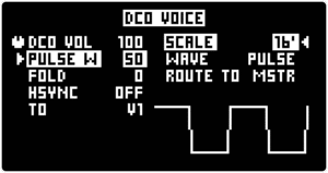
As an alternative, turn the DCO VOLUME knob and notice the momentary pop-up [DCO SETT ◁] on the the upper-right corner of the screen. While the pop-up is displayed press the ◁ RIGHT SCREEN ENCODER to enter the DCO SCREEN.
Turn the ◁ RIGHT SCREEN ENCODER to choose the [SCALE] of the DCO. Push the encoder again to toggle to the [SHAPE] selection row. Turn the ◁ RIGHT SCREEN ENCODER to choose between the available DCO Waveforms [WAVE]: “PULSE”, “SAW”, Triangle “TRI”, “SINE” and “NOISE”.
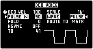
The following waveshaping parameters are available for “PULSE”, “SAW”, Triangle “TRI” and “SINE” Waveforms. These parameters can be used to alter the DCO shapes and change their harmonic content. Push the ▷ LEFT SCREEN ENCODER to toggle between them and turn the encoder to set the desired value.
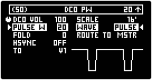
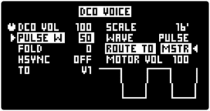
[PULSE W] controls the pulse width in percentage of one cycle. 0% and 100% pulse width are also possible. A unique version of this parameter is also available for the other non-pulse waveshapes.
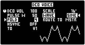
[FOLD] controls the wavefolding amount. Increasing the wavefolding amount results in added harmonics.
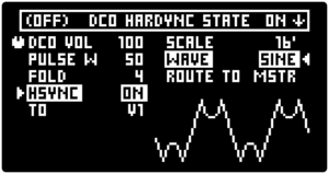
[HSYNC] is the DCO hard sync status. By default this parameter is set to the “OFF” state. Turning it “ON” allows it to hard sync the DCO to one of the MOTOR VOICES. With [HSYNC] turned “ON” the DCO waveform will be reset each time a new cycle starts for the MOTOR VOICE. In simple terms this will result in DCO having the same fundamental frequency as the MOTOR VOICE no matter what the DCO [SCALE] or DCO [DETUNE] is set to. The resulting sound is very dependent on the frequency relationship between the DCO and the MOTOR VOICE as well as all of the DCO parameters that affect its waveshaping and frequency. These parameters determine the harmonic content on top of the fundamental frequency, which won’t necessarily be the loudest harmonic.
The [TO] parameter determines which of the MOTOR VOICES the DCO will be hard synced to.
Tip: These waveshaping parameters are manually controlled. However, typically these parameters are modulated by an LFO or an envelope generator, for example an LFO controlled PWM bass line. The MOTOR SYNTH offers a wide range of modulation possibilities, please refer to the MODULATION section.
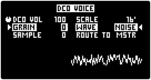
The final available DCO Waveform [WAVE] is “NOISE” which produces white noise. Noise can be useful for creating transients for percussive sounds, but there are many other potential applications. If a different color noise is required it can be created by filtering the NOISE waveshape with the DCO’s FILTER.
The “NOISE” waveform offers control over two types of sample rate parameters instead of the PULSEWIDTH, FOLD, and HARD SYNC controls.
[GRAIN] is a noise sample reduction parameter. As the parameter value is increased the sample rate is reduced. Sample rate reduction introduces audible pitch corresponding to the sample rate.
[SAMPLE] introduces a sampled loop of the noise. If set to 0 then the noise is not sampled. As the parameter value is increased, the sampled loop size is reduced resulting in audible pitch corresponding to the looping frequency.
There are multiple options for routing the DCO’s output. Push the ◁ RIGHT SCREEN ENCODER until the [ROUTE TO] parameter is highlighted and then turn the encoder to choose one of the following options:
“MSTR” – the default setting in which the DCO’s output is mixed together with the MOTOR VOICES at the final output mixer. In the SPLIT ROUTE setting the DCO’s output is present in both output channels.
“V1” – the DCO’s output is mixed with MOTOR VOICE 1 before the FILTER of V1. This allows the DCO to pass through its digital filter and then through the analog filter of the MOTOR VOICE. This setting is most suitable for using the DCO as a tonal extension of a MOTOR VOICE.
“V2” – the DCO’s output is mixed with MOTOR VOICE 2 before the FILTER of V2.
“V1+V2” – the DCO’s output is mixed both with MOTOR VOICE 1 and 2 before the FILTER of each MOTOR VOICE.
[MOTOR VOL] parameter reduces the motor volume before the FILTER.
Note: When the DCO's output is mixed with the MOTOR VOICES, it is passing through the voice's filter and final amp. This means that the final dynamic and harmonic sound characteristics are determined by the given MOTOR VOICE. Also the limited headroom of the FILTER can render one of the voices inaudible depending on DCO volume. [MOTOR VOL] parameter allows to reduce the motor output before the FILTER. This is useful for balancing the MOTOR VOICE and DCO volumes before the FILTER.
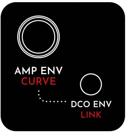
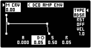
Apart from the difference in front panel access, the DCO AMP ENVELOPE functions the same as MOTOR VOICE AMP ENVELOPES. Please refer to section AMP ENVELOPE for further information.
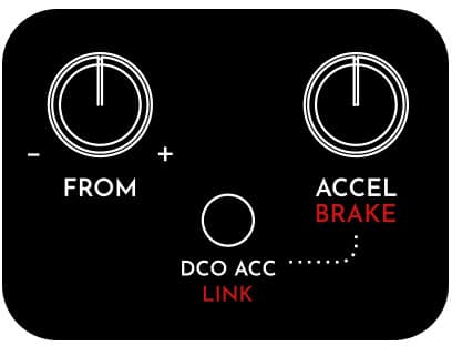
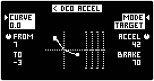
This will bring up the DCO ACCEL SCREEN. Now use the MOTOR VOICE 1 FROM / TO and ACCEL / BRAKE knobs and both SCREEN ENCODERS to adjust all of the DCO ACCELERATION / BRAKE parameters. Please refer to section ACCELERATION/BRAKE (PITCH ENVELOPE) for further information.