


MENU
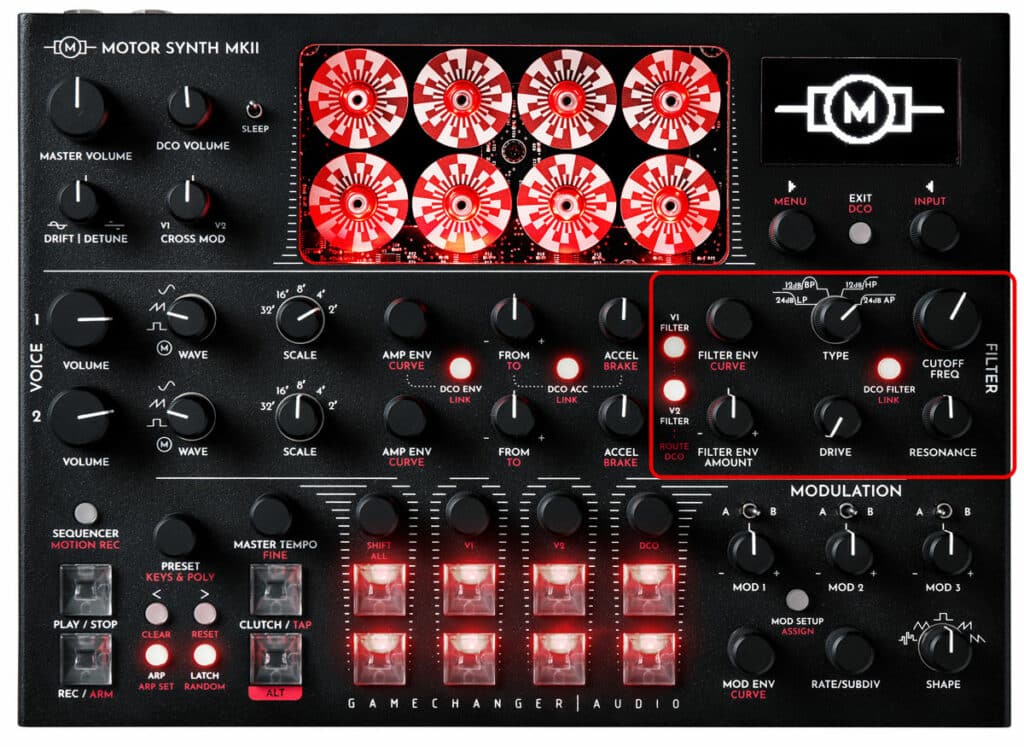
Note: The MOTOR Synth signal path before the FILTER is polyphonic where each motor and digital oscillator has a dedicated amplifier controlled by a individual envelope. The FILTER section is paraphonic, where all 4 motors of each MOTOR VOICE and all 4 oscillators of the DIGITAL VOICE are mixed together and passed through one FILTER.
| PARAMETER | CONTROL | DESCRIPTION | VALUE RANGE |
|---|---|---|---|
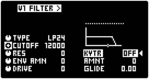
| Filer type [TYPE] | TYPE knob | Filter type selection | “LP24” 24dB Low Pass;
“BP12” 12dB Band Pass; “HP12” 12 dB High Pass; “AP24” 24 dB All Pass |
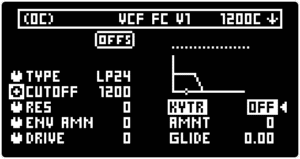
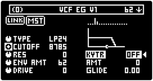
| [CUTOFF] | CUTOFF FREQ knob for coarse tuning & ▷ LEFT SCREEN ENCODER for fine tuning | The filter cutoff point in cents (default) or hertz depending on the settings in the SYSTEM MENU | From 20 to 21096 Hz or from 0 to 12000 cents relative to 20 Hz |
| Resonance [RES] | RESONANCE knob | Resonance amount | From 0 to 100. Self-oscillation starts at ∼87 |
| [DRIVE] | DRIVE knob | Drive circuit gain before the FILTER | From 0 (unity gain) to 100 (maximum distortion) |
| Envelope Amount [ENV AMT] | FILTER ENV AMOUNT knob | The amount of FILTER ENVELOPE modulation on [CUTOFF] | From -100 (Full amount, inverted), through 0, to 100 (full amount) |
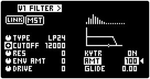
| Key Tracking [KYTR] | ◁ RIGHT SCREEN ENCODER | [CUTOFF] key tracking status | “OFF”; “ON” |
| Key Tracking Amount [AMT] | ◁ RIGHT SCREEN ENCODER | The key tracking amount | From -100 (Inverted tracking) through 0 to 100 (precise tracking) |
| Key Tracking Glide [GLIDE] | ◁ RIGHT SCREEN ENCODER | Key tracking gilde (slew / portamento) | From 0 to 5 |
| PARAMETER | CONTROL | DESCRIPTION | VALUE RANGE |
|---|---|---|---|
| Filer type [TYPE] | TYPE knob | Filter type selection | “LP24” 24dB Low Pass;
“BP12” 12dB Band Pass; “HP12” 12 dB High Pass; “AP24” 24 dB All Pass |
| [CUTOFF] | CUTOFF FREQ knob for coarse tuning & ▷ LEFT SCREEN ENCODER for fine tuning | The filter cutoff point in cents (default) or hertz depending on the settings in the SYSTEM MENU | From 20 to 21096 Hz or from 0 to 12000 cents relative to 20 Hz |
| Resonance [RES] | RESONANCE knob | Resonance amount | From 0 to 100. Self-oscillation starts at ∼87 |
| [DRIVE] | DRIVE knob | Drive circuit gain before the FILTER | From 0 (unity gain) to 100 (maximum distortion) |
| Envelope Amount [ENV AMT] | FILTER ENV AMOUNT knob | The amount of FILTER ENVELOPE modulation on [CUTOFF] | From -100 (Full amount, inverted), through 0, to 100 (full amount) |
| Key Tracking [KYTR] | ◁ RIGHT SCREEN ENCODER | [CUTOFF] key tracking status | “OFF”; “ON” |
| Key Tracking Amount [AMT] | ◁ RIGHT SCREEN ENCODER | The key tracking amount | From -100 (Inverted tracking) through 0 to 100 (precise tracking) |
| Key Tracking Glide [GLIDE] | ◁ RIGHT SCREEN ENCODER | Key tracking gilde (slew / portamento) | From 0 to 5 |
| PARAMETER | CONTROL | DESCRIPTION | VALUE RANGE | ||||
|---|---|---|---|---|---|---|---|
|
Filer type [TYPE] |
TYPE knob |
Filter type selection |
“LP24” 24dB Low Pass; |
||||
| PARAMETER | CONTROL | DESCRIPTION | VALUE RANGE | ||||
|---|---|---|---|---|---|---|---|
|
[CUTOFF] |
CUTOFF FREQ knob for coarse tuning & ▷ LEFT SCREEN ENCODER for fine tuning |
The filter cutoff point in cents (default) or hertz depending on the settings in the SYSTEM MENU |
From 20 to 21096 Hz |
||||
| PARAMETER | CONTROL | DESCRIPTION | VALUE RANGE | ||||
|---|---|---|---|---|---|---|---|
|
Resonance [RES] |
RESONANCE knob |
Resonance amount |
From 0 to 100. |
||||
| PARAMETER | CONTROL | DESCRIPTION | VALUE RANGE | ||||
|---|---|---|---|---|---|---|---|
|
[DRIVE] |
DRIVE knob |
Drive circuit gain before the FILTER |
From 0 (unity gain) to 100 (maximum distortion) |
||||
| PARAMETER | CONTROL | DESCRIPTION | VALUE RANGE | ||||
|---|---|---|---|---|---|---|---|
|
Envelope Amount [ENV AMT] |
FILTER ENV AMOUNT knob |
The amount of FILTER ENVELOPE modulation on [CUTOFF] |
From -100 (Full amount, inverted), through 0, to 100 (full amount) |
||||
| PARAMETER | CONTROL | DESCRIPTION | VALUE RANGE | ||||
|---|---|---|---|---|---|---|---|
|
Key Tracking [KYTR] |
◁ RIGHT SCREEN ENCODER |
[CUTOFF] key tracking status |
“OFF”; “ON” |
||||
| PARAMETER | CONTROL | DESCRIPTION | VALUE RANGE | ||||
|---|---|---|---|---|---|---|---|
|
Key Tracking Amount [AMT] |
◁ RIGHT SCREEN ENCODER |
The key tracking amount |
From -100 (Inverted tracking) through 0 to 100 (precise tracking) |
||||
| PARAMETER | CONTROL | DESCRIPTION | VALUE RANGE | ||||
|---|---|---|---|---|---|---|---|
|
Key Tracking Glide [GLIDE] |
◁ RIGHT SCREEN ENCODER |
Key tracking gilde (slew / portamento) |
From 0 to 5 |
||||
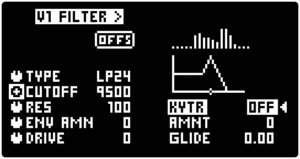
Once the FILTER SCREEN is active it is possible to toggle between the voices by using the < > buttons in the bottom left corner of the MOTOR Synth. This navigation option is suggested by the small arrow symbols [< >] at the top of the FILTER SCREEN.
Note: The FILTER Cutoff Frequency [CUTOFF] ranges from 20 to 21096 Hz. However, the default [CUTOFF] measurement unit is cents where 0 cents correspond to a frequency of 20 Hz or roughly E0 note. The measurement unit (hertz or cents) can be changed in the SETTINGS MENU. Using cents as a measurement unit is useful when utilizing the Keytrackng [KYTR]. Cents indicate the [CUTOFF] offset from the note pitch. For example, if Keytrack Amount [AMT] is set to 100 then setting the [CUTOFF] to 1200c will correspond to one octave above note pitch.
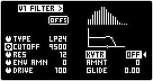
Turn the RESONANCE knob to set the Filter Resonance [RES] amount. Self-oscillation starts around value 87, but the effect depends on other parameters, like [CUTOFF] and [DRIVE].
Turn the DRIVE knob to set the [DRIVE] level. This will raise the output level of the VOICE, distort the signal and add more harmonic content before filtering.
Tip: Other instruments that utilize electromagnetic induction pickups, especially the electric guitar, are known to be used with distortion and filtering afterwards. In the case of the electric guitar, pedals and amplifiers introduce distortion that is filtered by guitar speakers. Similarly the harmonically rich motor electromagnetic induction sound responds well to distortion and filtering.
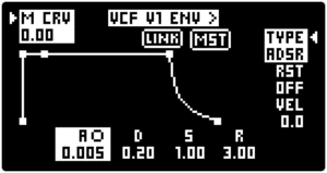
Turn the FILTER ENV AMOUNT knob to set the Envelope Amount [ENV AMT] for the [CUTOFF] parameter.
As the ENVELOPE AMOUNT Knob is a center indent potentiometer, it offers gradual positive and negative modulation amounts. In the center indent position the [ENV AMT] is zero.
The MOTOR Synth FILTERS are calibrated to precisely track pitch. The Key Tracking [KYTR] and related parameters determine how the FILTER tracks pitch. The FILTER will track the pitch of the last note played for the given voice.
Turn the ◁ RIGHT SCREEN ENCODER to toggle the [KYTR] between the “OFF” and “ON” states.
Push the ◁ RIGHT SCREEN ENCODER to highlight the Key Tracking Amount [AMT] parameter and turn the encoder to change the parameter’s value. The default value is 0 which produces no key tracking. The maximum value 100 provides precise key tracking. The minimum value -100 produces inverted key tracking.
Key Tracking [KYTR] modulates the [CUTOFF] parameter. In order for the [CUTOFF] frequency to match the note frequency, set the CUTOFF knob to the minimum position value 0c or 20 Hz and then set the Key Tracking Amount [AMT] to 100.
Tip: Even though setting [KYTR] to the ''OFF" position produces the same effect as setting the amount [AMT] to 0, the [KYTR] parameter can be quickly and easily toggled during a performance, while the [AMT] parameter remains set to a specific value. This can be very useful when performing with a self-oscillating FILTER that is being toggled between Keytracking and non-Keytracking modes.
Push and then turn the ◁ RIGHT SCREEN ENCODER to set the Key Tracking Glide [GLIDE] – an innovative parameter which adds slew (portamento) to the FILTER Key Tracking function.
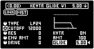
Tip: Because the FILTER is paraphonic, long Key Tracking Glide [GLIDE] values can be very useful when performing long polyphonic pads or ambiences. Without the [GLIDE}, whenever a new note is layered, the FILTER [CUTOFF] will suddenly change, thus causing the already playing notes to change their sound. Longer Key Tracking Glide [GLIDE] values help smooth out this unwanted effect.