MOD ASSIGN PROCESS
Each MODULATOR has a center-indent MOD DEPTH knob as well as two MOD Destination Slots - A and B. Use the dedicated A-B toggle to switch between the layers to control their MODULATION DEPTH and their MOD DESTINATION.
Each MODULATOR can be assigned to almost any parameter of the MOTOR Synth.
This can be done from any SCREEN except the MENU SCREENS.
Press ALT + MOD SETUP / ASSIGN button to enter the MOD ASSIGN SCREEN:
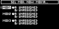
The MOD ASSIGN SCREEN gives you an overview of all of the current MODULATOR destinations, as well as lets you ARM one of the SIX MOD Slots by moving the three MOD Knobs and their A-B switches.
PRESS ALT + RESET to EXIT the MOD ASSIGN mode at any time.
In this example let’s choose SLOT MOD 2A by making sure that the MOD 2 switch is in the A position and MOVING MOD 2 knob slightly.
Press ALT + MOD SETUP / ASSIGN button to confirm the MOD SLOT selection and the MOD ASSIGN SCREEN will close:
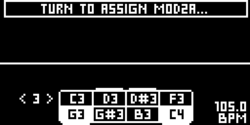
When you see the POP-UP above "TURN TO ASSIGN MOD 2A", it means that the MOD 2A slot is “ARMED”.
Now simply adjust any knob or switch on the MOTOR Synth’s front panel to ASSIGN it as the Destination for MOD2A.
For example - let's slightly move the FILTER CUTOFF FREQUENCY Knob.
Now MOD 2A is “ASSIGNED” to the CUTOFF FREQUENCY of ALL FILTERS as the Destination:
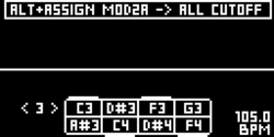
This is indicated by a new POP-UP on the SCREEN, and you will see a quick pulsation of the MOD SETUP / ASSIGN Button.
Now you can either CONFIRM the destination by holding ALT and pressing MOD SETUP / ASSIGN or change the destination by moving another knob on the MOTOR Synth’s front panel to “ASSIGN” a different parameter.
In this example - press ALT + MOD SETUP / ASSIGN button to confirm the MOD Destination.
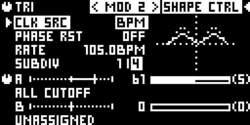
The ASSIGN Button will stop blinking and MOD2A will be assigned to ALL CUTOFF.
Press the MOD SETUP Button to open the MOD SETUP SCREEN:
Now let’s Repeat the procedure and use MOD 1A to modulate the depth of MOD 2:
1) PRESS ALT + MOD SETUP / ASSIGN
2) MOVE the MOD1 KNOB and press ALT + MOD SETUP / ASSIGN to CONFIRM and ARM the slot MOD1A:
3) NOW TURN MOD2 Depth Knob to assign it as the destination for MOD 1A
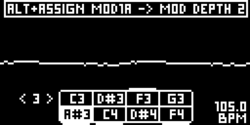
4) PRESS ALT + MOD SETUP / ASSIGN to Confirm.
5) Press MOD SETUP to open the MOD1 VIEW SCREEN. As you can see - MOD 1A is now moving the DEPTH of MOD 2A.
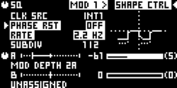
Use the < & > ARROW Buttons to navigate between the MODULATORS 1-3.

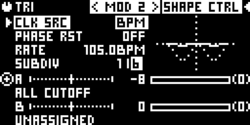
Here we have a very interesting case, because MODULATOR 1 is using an internal CLOCK Source and a SLEWED SQUARE Shape to Modulate the DEPTH OF MOD 2A which assigned to the All FILTER CUTOFF Frequency and using a 1/6 subdivision of the MASTER BPM and a Triangle Shape.
ANY PARAMETER that is assigned as an active MOD DESTINATION is indicated by this "Target" Symbol:
Now, let's take a look at how to assign MODULATORS to DESTINATIONS that do not have dedicated front panel controls (potentiometers or switches):
